|
|
|
CHAPTER 3: ENERGY AND MOMENTUM PRINCIPLES |
3.1 ENERGY PRINCIPLE
|
|
Under steady flow, mass and energy are conserved in open-channel flow.
On the other hand, under unsteady flow, mass and momentum are conserved.
Energy is expressed in FL units
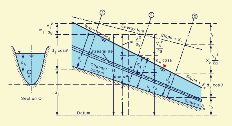
With reference to the channel of large slope of Fig. 3-1, the total head H at a section 0 containing point A on a streamline may be written as follows:
|
VA2 H = zA + dA cos θ + ______ 2g | (3-1) |
in which zA = elevation of point A above a datum plane, dA = depth of point A below the water surface, θ = slope angle of the channel bottom, and VA2/(2g) = velocity head of the flow in the streamline passing through point A.
|
Due to cross-sectional nonuniformity, the velocity head is likely to vary along the flow depth and width. In practice, at a given cross section, the velocity head is based on the mean velocity V for that cross section, and the Coriolis coefficient (Section 2.2) is used to account for the nonuniformity in the velocity distribution. This leads to the total energy for the channel section:
|
V 2 H = z + d cos θ + α _____ 2g | (3-2) |
For a channel of small slope, cos θ ≅ 1. Thus, the total energy reduces to:
|
V 2 H = z + d + α _____ 2g | (3-3) |
The statement of conservation of energy between cross sections 1 and 2 leads to (Fig. 3-1):
|
V12 V22 z1 + d1 cos θ + α1 _____ = z2 + d2 cos θ + α2 _____ + hf 2g 2g | (3-4) |
in which hf = energy loss.
The line representing the total head is the energy grade line (EGL) or energy line. The slope of the line is the energy gradient, or Sf. The slope of the water surface is denoted by Sw and the slope of the channel bottom is So, where So = tan θ. Under uniform flow conditions, all three slopes are the same: Sf = Sw = So.
For a channel of small slope, Eq. 3-4 reduces to:
|
V12 V22 z1 + y1 + α1 _____ = z2 + y2 + α2 _____ + hf 2g 2g | (3-5) |
When α1 = α2 ≅ 1 (a hydraulically wide channel), and hf = 0, Eq. 3-4 reduces to the statement of conservation of energy, or Bernoulli equation:
|
V12 V22 z1 + y1 + _____ = z2 + y2 + _____ = constant 2g 2g | (3-6) |
3.2 SPECIFIC ENERGY
|
|
Equation 3-6 is applicable to a channel of small slope. In the limit, when the channel is horizontal, or else, as an approximation, when the channel is sufficiently short, Eq. 3-6 simplifies to a statement of conservation of specific energy. In effect, for z1 ≅ z2, Eq. 3-6 reduces to:
|
V12 V22 y1 + _____ = y2 + _____ = constant 2g 2g | (3-7) |
Equation 3-7 states the constancy of specific energy in a hydraulically wide horizontal channel. The specific energy is:
|
V 2 E = y + _____ 2g | (3-8) |
where E is the energy per (unit of) weight, measured with respect to the channel bottom, defined in terms of the flow depth y and the velocity head V 2/(2g).
Since V = Q /A, the specific energy in terms of discharge is:
|
Q 2 E = y + _________ 2g A 2 | (3-9) |
Since Q is a constant under steady flow, and flow area A is always a unique function of flow depth y, the specific energy for a given Q is only a function of y.
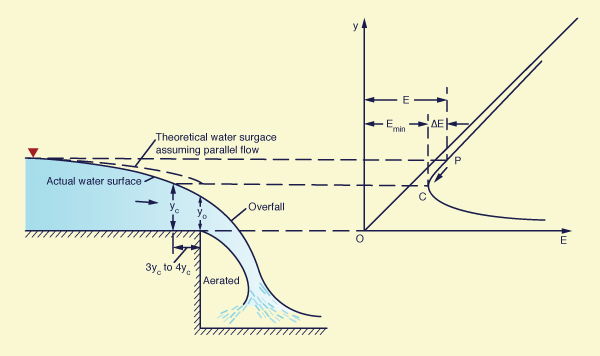
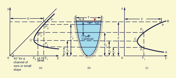
For a given cross section and discharge Q, a plot of flow depth y versus specific energy E leads to the specific energy curve. A typical curve is shown in Fig. 3-2. For a given Q, the specific energy curve is a type of hyperbolic function, featuring a minimum value of E and two limbs, a lower limb AC and an upper limb BC.
|
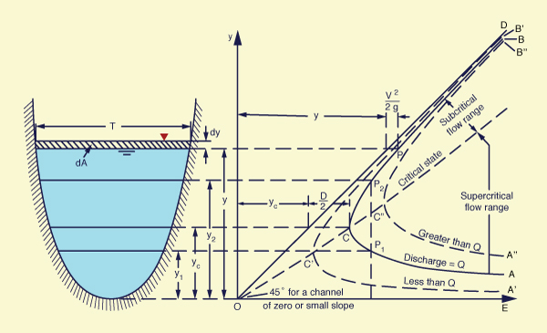
The minimum value of E (at point C) characterizes the critical state of flow, with critical depth. The lower limb AC, with smaller depths, describes supercritical flow. This limb is asymptotic to the horizontal axis. The upper limb BC, with larger depths, describes subcritical flow. This limb is asymptotic to a 45° line OD that originates at the origin (O). At any point P on the curve, the abscissa represents the specific energy E and the ordinate the flow depth y.
For a given specific energy, there are two points on the curve, one corresponding to low stage (small depth) and another corresponding to high stage (large depth). These depths are referred to as alternate depths. At point C, the alternate depths coalesce into one depth, termed the critical depth; at that point, the specific energy is a minimum. When the depth of flow is greater than the critical depth, the flow is termed subcritical. When the depth of flow is smaller than the critical depth, the flow is termed supercritical. For a discharge Q, the specific energy curve is curve AB in Fig. 3-2. For a smaller discharge, it is A'B'; for a larger discharge, it is A"B".
Critical flow criterion
From Fig. 3-2, critical depth (critical flow) corresponds to minimum specific energy. To prove this assertion mathematically, differentiate Eq. 3-9 with respect to y and equate to zero, to yield:
|
dE Q 2 dA ______ = 1 - _______ ______ = 0 dy g A 3 dy | (3-10) |
By definition, the differential change in flow area dA is equal to the top width T times the differential change in flow depth dy (Fig. 3-2):
|
dA = T dy | (3-11) |
Thus, Eq. 3-10 reduces to:
|
Q 2 Tc ________ = 1 g Ac 3 | (3-12) |
Since Dc = Ac /Tc , and Vc = Q /Ac , Eq. 3-12 reduces to:
|
Vc 2 ______ = 1 g Dc | (3-13) |
The left-hand side of Eq. 3-13 is effectively the square of the Froude number (Section 1-3). Thus, the condition F 2 = 1, or better yet, F = 1, properly describes the condition of critical flow, for which the specific energy is a minimum. Alternatively, Eq. 3-13 may be expressed as follows:
|
Vc 2 Dc ______ = _____ 2g 2 | (3-14) |
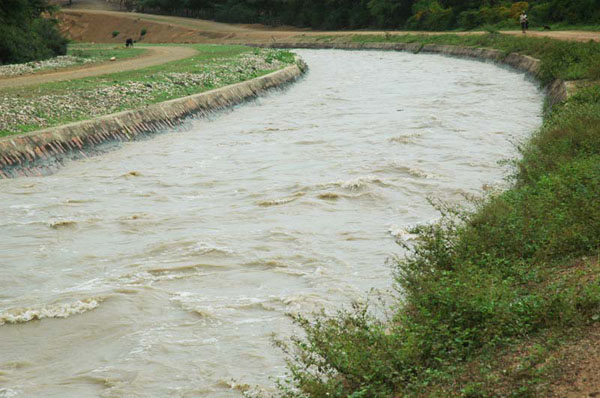
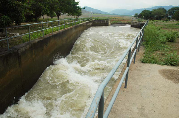
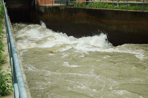
which states that, under critical flow, the velocity head is equal to one-half of the hydraulic depth. Figure 3-3 shows a channel operating at near critical flow.
|
Equation 3-14 describes the critical flow condition for a channel of small slope that is hydraulically wide (α = 1). In general, for a channel of large slope and arbitrary cross-sectional shape, the critical flow condition is:
|
Vc 2 Dc cos θ α ______ = __________ 2g 2 | (3-15) |
in which Dc is the hydraulic depth corresponding to critical flow, measured normal to the channel bottom. Thus, the general critical flow condition is:
|
Vc 2 _________________ = 1 (g Dc cos θ) / α | (3-16) |
and the general definition for Froude number, applicable to any channel, regardless of slope and cross-sectional shape, is:
|
V F = _____________________ [ (g D cos θ) / α ]1/2 | (3-17) |
3.3 LOCAL PHENOMENA
|
|
Changes from supercritical to subcritical flow, or from subcritical to supercritical flow, occur frequently in open-channel flow, depending on the prevailing channel slope and cross section. If the changes occur within a relatively short distance, they constitute local phenomena. The hydraulic drop and the hydraulic jump are examples of local phenomena.
The hydraulic drop
The hydraulic drop is triggered by a sharp depression in the water surface, usually caused by an abrupt change in bottom elevation. The free overfall shown in Fig. 3-4 is an example of a hydraulic drop.
|
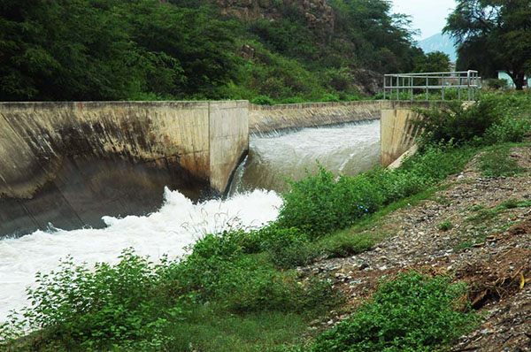
Flow in the proximity of a free overfall is usually rapidly varied; therefore,
the brink depth is somewhat smaller than the critical depth
computed by the theory of parallel flow. Figure 3-5 shows a schematic of the flow near the brink.
The actual drawdown curve is shown with a solid line,
while the theoretical water-surface curve, assuming parallel flow,
is shown with a dashed line.
For channels of small slope, the computed critical depth is about 1.4 times the brink depth;
i.e.,
|
The hydraulic jump
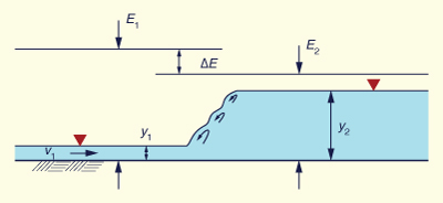
The hydraulic jump is caused by an abrupt rise in the water surface as the flow progresses downstream. In a hydraulic jump the flow changes from supercritical upstream to subcritical downstream, accompanied by an appreciable loss of energy. The amount of energy loss depends on the upstream and downstream flow conditions.
The jump occurs frequently under one of the following situations:
Below a regulating sluice gate (Fig. 3-6),
At the toe (or foot) of a spillway, or
At the location along the channel where the bottom slope suddenly changes from steep to mild.
|
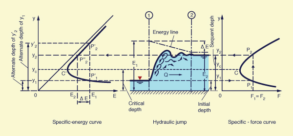
The flow depth before the jump is called the initial depth y1, while the flow after the jump is called the sequent depth y2. The initial and sequent depths y1 and y2 are shown on the specific energy curve of Fig. 3-7. They should be distinguished from the alternate depths y1 and y2', which are two possible depths for the same specific energy.
The specific energy E1 at the initial depth y1 is greater than the specific energy E2 at the sequent depth y2. The energy loss due to the hydraulic jump is the difference between specific energies for initial and sequent depths:
|
ΔE = E1 - E2 | (3-18) |
Also shown, to the right of Fig. 3-7, is the specific force curve (Section 3.5), where the sequent depths y1 and y2 have the same specific force: F1 = F2.
|
3.4 MOMENTUM PRINCIPLE
|
|
Momentum M is equal to a force integrated over a period of time, or mass times velocity, Eq. 2-27, repeated here for convenience:
|
M = ∫ F dt = m V ... [M L T -1 ] | (3-19) |
The momentum flux, or force F, of a flow with velocity V through a cross section of area A, Eq. 2-30, repeated here, is:
|
F = β ρ V 2 A ... [F] | (3-20) |
Since Q = VA, the momentum flux, or force F, exerted by a flow of discharge Q and velocity V is:
|
F = β ρ Q V ... [F] | (3-21) |
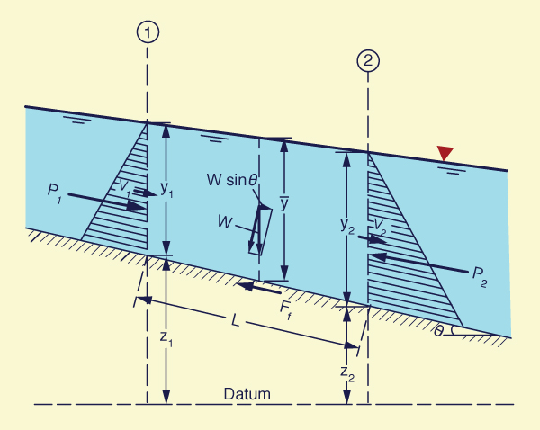
According to Newton's second law of motion, the change ΔF in momentum flux through a control volume is equal to the resultant of all the external forces acting on the control volume. The external forces are: (1) body force, and (2) surface forces. The body force is the gravitational force, resolved along the direction of motion (the force labeled W sinθ in Fig. 3-8). In general, there is a nonzero channel bottom slope θ; otherwise, the channel bottom would be horizontal and the gravitational component along the direction of motion would vanish.
The surface forces on the control volume are of three kinds: (1) on the bottom, (2) on the sides, and (3) on the top. The bottom surface force is due to friction, which is always acting in the direction opposite to the flow (the force labeled Ff in Fig. 3-8). There is no such thing as zero friction; under certain conditions, friction may be neglected, but it is never zero.
The side surface forces are two:
one upstream, the force labeled P1 in Fig. 3-8,
and another downstream, the force labeled P2. These forces are
due to the water pressure, which is
either hydrostatic under parallel flow, or nonhydrostatic under convex or concave
curvilinear flow
(
The top surface force is due to wind. Under the scales normally considered in open-channel flow, wind forces are small and are usually neglected. However, wind forces may not be negligible in cases on free-surface flow in reservoirs or flow in a wide open space such as the ocean.
The statement of momentum (flux) conservation in a control volume is (Fig. 3-8):
|
ρ Q (β2V2 - β1V1) = P1 - P2 + W sin θ - Ff ... [F] | (3-22) |
Or, in terms of unit weight:
|
(γ/g) Q (β2V2 - β1V1) = P1 - P2 + W sin θ - Ff ... [F] | (3-23) |
|
Following the usual convention of mechanics, the momentum flux difference is equal to the flux at the downstream section 2 minus the flux at the upstream section 1. The forces acting on the control volume are positive in the flow direction and negative against it. Equation 3-23 is known as the momentum flux balance equation or, for short, the momentum equation.
For parallel flow in a rectangular channel of small slope and width b, the force P1 is:
|
P1 = (1/2) γ b y12 ... [F] | (3-24) |
Similarly, the force P2 is:
|
P2 = (1/2) γ b y22 ... [F] | (3-25) |
The weight W of the control volume (Fig. 3-8) is:
|
W = (1/2) γ b L (y1 + y2) ... [F] | (3-26) |
The weight of the control volume, resolved along the direction of motion (Fig. 3-8), is:
|
W sin θ = (1/2) γ b (y1 + y2) (z1 - z2) ... [F] | (3-27) |
Generally, under typical gradually varied flow conditions, the friction force Ff along the channel bottom is about equal and opposite in sign to the gravitational force W sin θ (Eq. 3-27). Thus, the friction force may be expressed as follows:
|
Ff = (1/2) γ b (y1 + y2) hf' ... [F] | (3-28) |
in which hf' = head loss due to friction.
The discharge Q is:
|
Q = (1/2) (V1 + V2)
b (1/2) (y1 + y2)
... [L3 T -1]
| (3-29) |
Substituting Eqs. 3-24 to 3-29 into Eq. 3-23 and simplifying terms, the following equation is obtained:
|
V12 V22 z1 + y1 + β1 _____ = z2 + y2 + β2 _____ + hf' 2g 2g | (3-30) |
Equation 3-30 differs from Eq. 3-5 in several important respects:
Energy is a scalar, therefore, Eq, 3-5 is a scalar equation; on the other hand, momentum is a vector, therefore, Eq. 3-30 is derived from a vector equation.
The velocity distribution coefficients are not the same; while the Coriolis coefficients apply to Eq. 3-5, the Boussinesq coefficients apply to Eq. 3-30.
The energy head loss hf of Eq. 3-5 measures internal losses throughout the control volume, while the friction head loss hf' of Eq. 3-30 measures external losses due to the action of surface forces on the control volume.
Thus, while Eqs. 3-5 and 3-30 look similar, they are not equivalent.
Equation 3-5 applies to steady gradually varied flow, while
Eq. 3-30 applies for unsteady gradually varied flow.
In other words,
In practice, the momentum principle applies to problems where forces can be shown to play a significant role. Typically, problems of steady gradually varied flow use conservation of energy, while problems of unsteady gradually varied flow use conservation of momentum. The exception is the hydraulic jump, which is rapidly varied. Both energy and momentum principles are used in the solution of the hydraulic jump.
3.5 SPECIFIC FORCE
|
|
In horizontal channels, the gravitational force resolved along the direction of motion is effectively zero. As a convenient approximation, for nearly horizontal channels, the gravitational force may be considered small and be neglected on practical grounds.
The frictional force develops along the channel bottom; the longer the channel, the greater the frictional force. Thus, for a short channel, the frictional force may be taken as sufficiently small and neglected on practical grounds. Note that the frictional force is never zero; its neglect is only justified as an approximation, when compared with the other forces that are present in open-channel flow.
The neglect or elimination of the gravitational and frictional forces in the momentum flux balance reduces it to:
|
(γ/g) Q (β2V2 - β1V1) = P1 - P2 ... [F] | (3-31) |
Assuming β1 = β2 = 1, Eq. 3-31 reduces to:
|
(γ/g) Q (V2 - V1) = P1 - P2 ... [F] | (3-32) |
Since V1 = Q / A1, and V2 = Q / A2:
|
Q 2 Q 2 (γ/g) ( ______ - ______ ) = P1 - P2 ... [F] A2 A1 | (3-33) |
The pressure force P acting on a cross-section of area A and distance z̄ from the centroid of the area to the water surface [Fig. 3-9 (b)] is:
|
P = γ z̄ A ... [F] | (3-34) |
|
Thus:
|
P1 = γ z̄1 A1 ... [F] | (3-35) |
|
P2 = γ z̄2 A2 ... [F] | (3-36) |
Substituting Eqs. 3-35 and 3-36 into Eq. 3-33, and dividing by unit weight γ :
|
Q 2 Q 2 ______ + z̄1 A1 = ______ + z̄2 A2 ... [L 3] gA1 gA2 | (3-37) |
In general, the specific force is defined as follows:
|
Q 2 F = ______ + z̄ A ... [L 3] gA | (3-38) |
Equation 3-37 states that specific force is conserved in open-channel flow in a short horizontal channel, i.e., F1 = F2. Note that specific force is a force per unit of γ, the weight per unit of volume; therefore, specific force has the units of volume [L3].
The specific force curve shown in Fig. 3-9 (c) is obtained by plotting F in the abscissas and y in the ordinates. This curve is similar to the specific energy curve [Fig. 3-9 (a)], but with significant differences. The limb AC approaches the horizontal axis asymptotically toward the right. The limb BC rises upward and extends without limit to the right.
For a given value of specific force F1, the curve has two possible depths: y1 and y2.
These are the initial and sequent depths of a hydraulic jump, respectively.
At point C [Fig. 3-9 (c)], the sequent depths coalesce into one depth, termed the critical depth; at that point, the specific force is a minimum.
Note that this is the same critical depth obtained by specific energy considerations; see
Critical flow criterion for specific force
As in the case of specific energy, to prove that minimum specific force corresponds to the critical flow criterion, differentiate Eq. 3-38 with respect to y to yield:
|
dF Q 2 dA d(z̄A) ______ = - _______ ______ + ________ = 0 dy g A 2 dy dy | (3-39) |
For a change in depth dy, the corresponding change d(z̄A) in the static moment of the water area about the free surface is equal to:
|
d(z̄A) = [A (z̄ + dy) + (1/2) T (dy)2] - z̄A | (3-40) |
As usual in differential calculus, the second-order term in Eq. 3-40 is neglected, to yield:
|
d(z̄A) = A dy | (3-41) |
Therefore, Eq. 3-39 reduces to:
|
dF Q 2 dA ______ = - _______ ______ + A = 0 dy g A 2 dy | (3-42) |
Simplifying Eq. 3-42:
|
Q 2 dA ______ ______ = A g A 2 dy | (3-43) |
Since dA /dy = T, Q /A = V, and A /T = D, Eq. 3-43 reduces to:
|
V 2 ______ = 1 g D | (3-44) |
which is the square of the Froude number:
|
Vc 2 F 2 = ______ = 1 g Dc | (3-45) |
Equation 3-45 is the criterion for critical flow, applicable to both specific energy and specific force (specific momentum) curves.
Note that the sequent depth y2 is always smaller than the high alternate depth y2' (Fig. 3-7). Furthermore, the energy E2 is always smaller than the energy E1, while the specific force F2 remains equal to the specific force F1 [Fig. 3-7 and Fig. 3-9 (c)]. In order to maintain a constant specific force, the flow depth must increase from y1 to y2 at the cost of losing a certain amount of energy. The energy loss is equal to: ΔE = E1 - E2. This situation occurs in the hydraulic jump, where the specific forces before and after the jump are equal, but with a consequent loss of energy (Fig. 3-10).
|
Specific force per unit of channel width
In a hydraulically wide channel, the specific force per unit of channel width b is:
|
F q 2 y 2 ___ = _____ + _____ ... [L 2] b gy 2 | (3-46) |
where q = Q /b.
In terms of mean velocity V = q/y, the specific force per unit of channel width b is:
|
F V 2y y 2 ___ = _______ + _____ ... [L 2] b g 2 | (3-47) |
Specific force in units of force
In units of force, the specific force is:
|
γQ 2 γF = _______ + γ z̄ A ... [F] gA | (3-48) |
In units of force, the specific force per unit of channel width b is:
|
γF γq 2 γy 2 ____ = ______ + ______ ... [F L -1] b gy 2 | (3-49) |
In units of force, and in terms of mean velocity V, the specific force per unit of channel width b is:
|
γF γV 2y γy 2 ____ = _________ + _____ ... [F L -1] b g 2 | (3-50) |
|
Example 3-1: The hydraulic jump equation Derive the relation between the initial (y1) and sequent (y2) depth in a hydraulic jump (Eq. 9-13) on a horizontal floor in a rectangular channel (Fig. 3-11).
From Eq. 3-47, the specific force balance between upstream (1) and downstream (2) of the hydraulic jump:
Replacing F1 = V1 /(gy1)1/2:
Factoring:
The solution of the quadratic equation within brackets is:
which is the same as Eq. 9-13. |
QUESTIONS
|
|
What is the difference between total energy and specific energy?
What is critical flow in terms of specific energy?
What causes a hydraulic drop?
Why is the flow depth at a free overfall less than critical?
What causes a hydraulic jump?
Why is momentum unsteady?
What is the body force considered in open-channel flow?
What is the magnitude of the body force in a horizontal channel?
What is the difference between alternate depths and sequent depths?
Where does specific force apply?
For what type of problems is specific force used?
PROBLEMS
|
|
Derive the relation for the discharge per unit of width q under a sluice gate, as a function of upstream depth y1 and downstream depth y3 (Fig. 3-12).
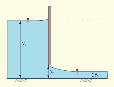
Fig. 3-12 Discharge under a sluice gate.
[See also Lab video: Sluice gate]. Prove that the equation derived in the previous problem (Problem 1) is mathematically equivalent to the equation based on y1 and y2 used in ONLINE CHANNEL 13.
Using the specific energy principle, derive the formula for the dimensionless throat width of a channel constriction that forces critical flow through it (Fig. 3-13) [Henderson (1966), p. 267].
bc (27)1/2 F1
σ = _____ = _______________
b1 (2 + F12) 3/2(3-55) 
Fig. 3-13 Critical width constriction using specific energy.
Use ONLINE CHANNEL 17 to calculate the required throat width bc for the following upstream conditions: y1 = 2.2 m, v1 = 1.2 m/s, and b1 = 3.2 m. What would be the required throat width if the upstream channel width is b1 = 2.2 m?
Using the specific force principle, show that the force fo (in kN/m) exerted by a blunt obstruction at the bottom of a wide rectangular channel is:
1 - α 2 1
fo = - γ y12 [ ________ + ( 1 - _____ ) F12 ]
2 α(3-56) where γ = unit weight of water, F1 = upstream Froude number, y1 = upstream flow depth, and
α = y2/y1, where y2 = downstream flow depth (after the obstruction). Given q = 1.5 m2/s,v1 = 1.0 m/s, and α = 0.91, calculate the force fo. Assuming the flow is from left to right, in what direction is the force fo acting?Using the specific force principle, derive the formula for the dimensionless throat width of a channel constriction that forces critical flow through it (Fig. 3-14) [modified from Henderson (1966), p. 267].
bc (3)3/4 F3
σ = _____ = _________________
b3 (1 + 2 F32) 3/4(3-57) 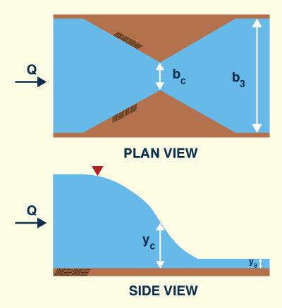
Fig. 3-14 Critical width constriction using specific force.
Using ONLINE LIMITING CONTRACTION, calculate the limiting contraction ratios using both energy and momentum principles, for a Froude number F = 0.3.
Using ONLINE LIMITING CONTRACTION SET, calculate the limiting contraction ratios using both energy and momentum principles, for Froude numbers is the range 0.1 ≤ F ≤ 2.0, at intervals of 0.1. Discuss the results.
A submerged hydraulic jump occurs immediately downstream of a sluice outlet in a rectangular channel. Using the momentum principle, prove that the ratio of submerged depth ys to tailwater depth y2 is:
ys y2
_____ = [ 1 + 2 F22 ( 1 - _____ ) ] 1/2
y2 y1(3-58) 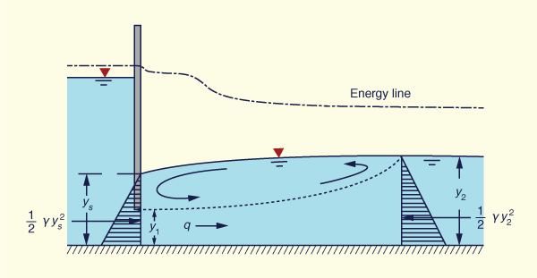
Fig. 3-15 A submerged hydraulic jump at a sluice outlet.
REFERENCES
|
|
Chow, V. T. 1959. Open-channel Hydraulics. McGraw Hill, New York.
Henderson, F. M. 1966. Open channel flow. Macmillan, New York.
| http://openchannelhydraulics.sdsu.edu |
|
141110 11:20 |