[Culverts]   [Inlet Control]   [Outlet Control]   [Culvert Design]   [Questions]   [Problems]   [References]     

CHAPTER 8:
CULVERT HYDRAULICS


8.1  CULVERTS

[Inlet Control]   [Outlet Control]   [Culvert Design]   [Questions]   [Problems]   [References]      [Top]  

Culverts are hydraulically short drainage conduits placed in locations where the drainage network intersects the transportation network (roads, railroad tracks). Culverts differ from bridges in that they are much smaller; thus, there are many more culverts than bridges. Culverts are designed to operate under gradually varied flow; therefore, the principles of Chapter 7 are applicable.

Culverts are designed to pass the design discharge without overtopping of the superstructure. The design discharge is derived from the design storm, which is based on hydrologic considerations. The return period (the reciprocal of the frequency) typically varies from 10 to 50 years. The longer the return period, the greater the design discharge and, therefore, the larger the required culvert size (Fig. 8-1).

Fig. 8-1  Large culvert at Yogurt Canyon, U.S.-Mexico international border, California.

The flow in a culvert is a function of:

  1. Cross-sectional size and shape,

  2. Bottom slope,

  3. Barrel length,

  4. Roughness, and

  5. Entrance and exit characteristics.

The flow in a culvert may be either (a) completely free-surface (open-channel flow), (b) completely closed-conduit (pipe flow), or (c) partially free-surface and closed-conduit flow. Headwater (HW) is the depth of water above the culvert invert at the inlet. Tailwater (TW) is the depth of water above the culvert invert at the outlet. The design headwater and tailwater elevations are major factors in determining whether the culvert flows partially full or completely full.

The design objective is to find the most economical design (i.e., the smallest culvert size) that will pass the design discharge without exceeding a specified headwater elevation (Fig. 8-2). The design depends on whether the culvert flow is under: (a) inlet control, or (b) outlet control.

Fig. 8-2  Large culvert crossing a railroad embankment, Tecate, Baja California, Mexico.


8.2  INLET CONTROL

[Outlet Control]   [Culvert Design]   [Questions]   [Problems]   [References]      [Top]   [Culverts]  

Culvert flow is under inlet control when the discharge depends only on the conditions at the inlet. Assume a circular culvert of diameter D, length L, slope S, headwater depth HW, and tailwater depth TW. Calculate the normal depth yn and the critical flow depth yc . Then, the following conditions hold:

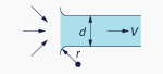
  • If yn < yc , the flow in the culvert barrel is supercritical and the tailwater has no influence on the upstream conditions (Fig. 8-3). Therefore, the headwater is solely controlled by the conditions at the inlet.

    Culvert flow under supercritical conditions, with inlet submerged and outlet
not submerged, i.e., free to the atmosphere

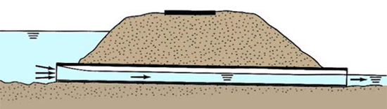
    Fig. 8-3  Culvert flow under supercritical conditions, with inlet submerged
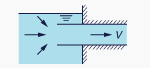
    and outlet unsubmerged.

  • If TW > yn, a hydraulic jump may form at or near the culvert outlet (Fig. 8-4).

    Culvert flow under supercritical conditions, with inlet submerged and outlet
submerged due to high tailwater

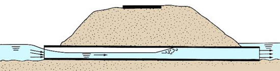
    Fig. 8-4  Culvert flow under supercritical conditions, with inlet unsubmerged
    and outlet submerged due to high tailwater.

Occurrence of inlet control

Inlet control occurs when the culvert barrel is capable of conveying more discharge than the inlet will allow. The control section is located just inside the entrance of the culvert. The flow passes through critical depth at the control section and becomes supercritical downstream of the inlet.

Under inlet control, the culvert acts as an orifice or weir. If the inlet is submerged (a common design situation), the flow condition resembles that of an orifice. If the inlet is unsubmerged (i.e., open to the atmosphere), the flow condition resembles that of a weir. [If HW < 1.2 D, the inlet will be unsubmerged]. If the inlet is unsubmerged but the outlet is submerged, a hydraulic jump will form inside the culvert barrel.


8.3  OUTLET CONTROL

[Culvert Design]   [Questions]   [Problems]   [References]      [Top]   [Culverts]   [Inlet Control]  

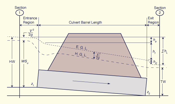
Outlet control occurs when TW > 1.2 D, i.e., for high tailwater. In this case, the culvert barrel will be completely full of water, resembling closed-conduit flow. The headwater may be computed by applying the energy equation from the upstream (u/s) pool elevation to the downstream (d/s) pool elevation. The headwater is directly controlled by the tailwater elevation and the frictional characteristics of the culvert barrel.

Occurrence of outlet control

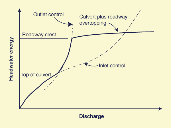
Outlet control occurs when inlet and outlet are submerged. Outlet control also occurs when the culvert slope is mild (subcritical flow) and both the headwater and tailwater are less than the culvert diameter (HW < D; TW < D). In this case, the best approach is to calculate the water-surface profile. Figure 8-5 shows a schematic portrayal of flow rate as a function of headwater energy under inlet and outlet control (U.S. Army Corps of Engineers, 2014).

Flow rate 
as a function of headwater energy under inlet and outlet control

Fig. 8-5  Discharge as a function of headwater energy under inlet and outlet control
(U.S. Army Corps of Engineers, 2014).


8.4  CULVERT DESIGN

[Questions]   [Problems]   [References]      [Top]   [Culverts]   [Inlet Control]   [Outlet Control]  

The following steps are followed in culvert design:

  1. Assemble design data

    • Discharge,

    • Tailwater elevation, and

    • Slope of culvert barrel.

  2. Choose the culvert characteristics

    • Cross-sectional shape (circular, square, rectangular, arch),

    • Dimensions (diameter, if circular),

    • Barrel length,

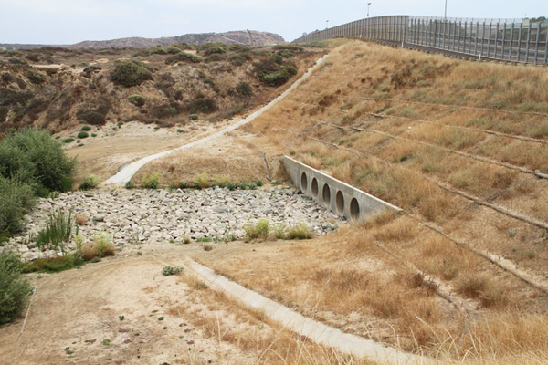
    • Kind of material (Figs. 8-6 and 8-7) (concrete, corrugated steel, corrugated aluminum, stone masonry), and

    • Type of entrance (square-edged or rounded).

    Culverts made with corrugated aluminum

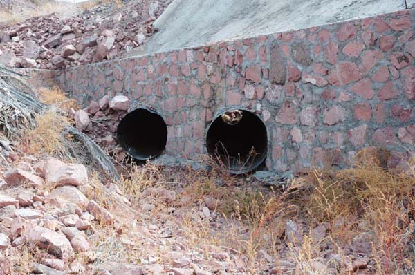
    Fig. 8-6  A set of two culverts made with corrugated steel.

  3. Ascertain the prevailing type of control (inlet or outlet), based on (a) headwater elevation, (b) tailwater elevation, (c) diameter, and (d) slope.

  4. If inlet control prevails, calculate the required headwater elevation to pass the design discharge.

  5. If outlet control prevails, calculate the required headwater elevation using (a) the energy equation or (b) water-surface profile computations.

  6. If the calculated headwater elevation is greater than allowed, choose a larger-size culvert and repeat the process.

  7. In some cases, it may not be possible to determine the type of control a priori. In this case, both calculations are advised. The design type of control is that which results in the greatest headwater elevation.

  8. Other design considerations in culvert design

    • Piping in the embankment surrounding the culvert,

    • Local scour at culvert outlet,

    • Erosion of fill material near the inlet,

    • Clogging with excessive debris, and

    • Provision for fish passage.
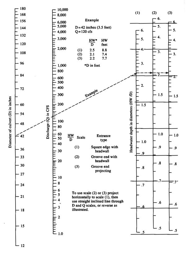
A rectangular stone-masonry culvert.

Fig. 8-7  A highway underpass featuring a rectangular stone-masonry culvert.


Design Example

Design a culvert for the following conditions:

  • Design discharge:  Q = 200 cfs.

  • Return period:  T = 25 yr.

  • Barrel length:  L = 200 ft.

  • Bottom slope:  So = 0.01.

  • Culvert material:  Concrete.

  • Manning's n = 0.013.

  • Inlet invert elevation:  z1 = 100 ft.

  • Roadway shoulder elevation:  Es = 110 ft.

  • Tailwater depth above outlet invert:  TW = y2 = 3.5 ft.

  • Freeboard:  Fb = 2 ft.


Solution

  • The design elevation for the upstream pool is:  Es - Fb = 100 - 2 = 108 ft.

  • Assume a circular concrete pipe, with square edge with headwalls.

  • Assume outlet control.

  • Assume that the hydraulic grade line (HGL) is at the elevation of the downstream pool.

  • Calculate the outlet invert elevation: z2 = z1 - (So L) = 100 - (0.01 × 200) = 98 ft.

  • Calculate the downstream pool elevation:  z2 + y2 = 98 + 3.5 = 101.5 ft.

  • Set up the energy balance (Fig. 8-8):

                         V12                             V22
    z1  +  y1  +   _____  =  z2  +  y2  +   _____  +  ∑hL
                          2g                              2g
    (8-1)

    Energy balance in culvert flow

    Fig. 8-8  Energy balance in culvert flow.

  • Assume V1 = 0, i.e., the velocity is zero in the upstream pool.

  • Assume V2 = 0, i.e., the velocity dissipates to zero in the downstream pool.

  • The head loss ∑hL is equal to the sum of entrance losses (with loss coefficient Ke), exit losses (with loss coefficient KE), and barrel losses.

  • Using the Darcy-Weisbach equation, the head loss is:

                                                          V 2
    hL  =  [ (Ke  +  KE  +  f (L / D ) ] _____
                                                          2g
    (8-2)

  • From Table 8-1, assume Ke = 0.5 and KE = 1 (Roberson et al., 1985).

    Table 8-1  Loss coefficients in pipe entrance, contraction, and expansion.
    Description Sketch
    (Click on figure to display)
    Additional
    data
    Loss
    coefficient K
    Pipe entrance

    hL = Ke [V 2/(2g)]

    r /d Ke
    0.0 0.50
    0.1 0.12
    > 0.2 0.03
      1.0
    Contraction

    hL = KC [V22/(2g)]

    D2 /D1 KC
    θ = 60°
    KC
    θ = 180°
    0.0 0.080.50
    0.2 0.080.49
    0.4 0.070.42
    0.6 0.060.32
    0.8 0.05 0.18
    0.9 0.040.10
    Expansion

    hL = KE [V12/(2g)]

    D1 /D2 KE
    θ = 10°
    KE
    θ = 180°
    0.0  1.00
    0.2 0.130.92
    0.4 0.110.72
    0.6 0.060.42
    0.8 0.03 0.16

  • The relation between Darcy-Weisbach friction factor f and Manning's n is (Chapter 5):

               8 g n 2
    f  =  __________
              k 2R 1/3
    (8-3)

    in which k = 1 in SI units, and k = 1.486 in U.S. Customary units.

  • In U.S. Customary units, with k = 1.486, and g = 32.17 ft/s2:

              116.55 n 2
    f  =  ____________
                 R 1/3
    (8-4)

  • For a circular pipe: R = D / 4. Therefore:

             185.01 n 2
    f  =  ____________
                 D 1/3
    (8-5)

  • From Eq. 8-1, the energy balance reduces to:

                                                      
    z1  +  y1  =  z2  +  y2  +  ∑hL
                          
    (8-6)

                                                      
    108  =  101.5  +  ∑hL
                          
    (8-7)

    The head loss equation (Eq. 8-2) is repeated here for convenience:

                                                          V 2
    hL  =  [ (Ke  +  KE  +  f (L / D ) ] _____
                                                          2g
    (8-2)

    Replacing Eq. 8-5 in Eq. 8-2:

                                                                               V 2
    hL  =  [ 0.5  +  1.0  +  (185.01 n 2 L / D 4/3 ) ] _____
                                                                               2g

    (8-8)

    Combining Eqs. 8-7 and 8-8:

                                                        V 2
    6.5  =  [ 1.5  +  (6.253 / D 4/3 ) ] _____
                                                        2g
    (8-9)

  • The flow velocity is:  V = Q / A.

    Therefore: V = 200 / A = 200 / [ (π/4) D 2 ]

  • The velocity head is:  V 2 / (2g) = { 2002 / [ (π/4)2 D 4 ] } / (2g) = 1008 / D 4

  • Replacing the velocity head in Eq. 8-9:

                                                        1008
    6.5  =  [ 1.5  +  (6.253 / D 4/3 ) ] _______
                                                          D 4
    (8-10)

  • Solving Eq. 8-10 by iteration: D = 4.38 ft. For design purposes, assume the next larger size:  D = 4.5 ft.

  • With Q = 200 cfs, D = 4.5 ft = 54 in, enter Fig. 8-9 to find the ratio of headwater depth to diameter HW/D = 2.2, for the case of square edge with headwalls (1).

    Headwater to diameter ratio for concrete culverts with inlet control

    Fig. 8-9  Headwater depth for concrete culverts with inlet control.

  • The headwater depth is:  HW = (HW/D) × D = 2.2 × 4.5 = 9.9 ft.

  • The upstream pool elevation is:   100 + 9.9 = 109.9 ft. This upstream pool elevation is greater than 108 ft; therefore, it is too large. The chosen D = 4.5 ft is too small. Try the next size:  D = 5 ft.

  • With Q = 200 cfs, D = 5.0 ft = 60 in, enter Fig. 8-7 to find the ratio of headwater depth to diameter HW/D = 1.6, for the case of square edge with headwalls (1).

  • The headwater depth is:  HW = HW/D × D = 1.6 × 5.0 = 8.0 ft.

  • The upstream pool elevation is:   100 + 8.0 = 108.0 ft. This upstream pool elevation is the same as the design elevation; therefore, the design is now OK.

  • Calculate the normal depth using ONLINE CHANNEL 06:  yn = 3.284 ft.

  • Calculate the critical depth using ONLINE CHANNEL 07:  yc = 4.037 ft.

  • Since yn < yc, the flow is supercritical.

  • Since TW = 3.5 > yn = 3.284, there will be a small hydraulic jump at or near the outlet.

  • Since the flow is supercritical for most of the culvert length, it is concluded that inlet control prevails.

  • The design diameter is:  D = 5 ft = 60 in.  ANSWER.


QUESTIONS

[Problems]   [References]      [Top]   [Culverts]   [Inlet Control]   [Outlet Control]   [Culvert Design]  

  1. What is a culvert?

  2. What is the typical return period for culvert design?

  3. When is a culvert under inlet control?

  4. When is a culvert under outlet control?

  5. List the hydraulic variables affecting culvert flow.

  6. List other considerations in culvert design.


PROBLEMS

[References]      [Top]   [Culverts]   [Inlet Control]   [Outlet Control]   [Culvert Design]   [Questions]  

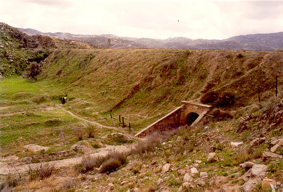
  1. Design a circular concrete culvert with the following data:  Q = 300 cfs; inlet invert elevation z1 = 100 ft; tailwater depth y2 = 4 ft; barrel slope So = 0.02; barrel length L = 200 ft; Manning's n = 0.013; roadway shoulder elevation Er = 112 ft; upstream freeboard Fb = 2 ft. The entrance type is square edge with headwalls (Fig. 8-10). Use ONLINECHANNEL 06 to calculate normal depth and ONLINECHANNEL 07 to calculate critical depth in the culvert.

    Typical culvert underpass

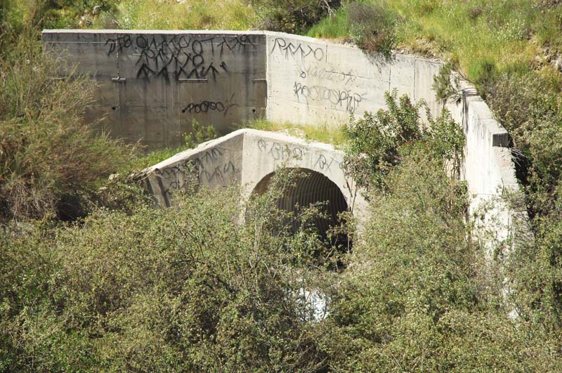
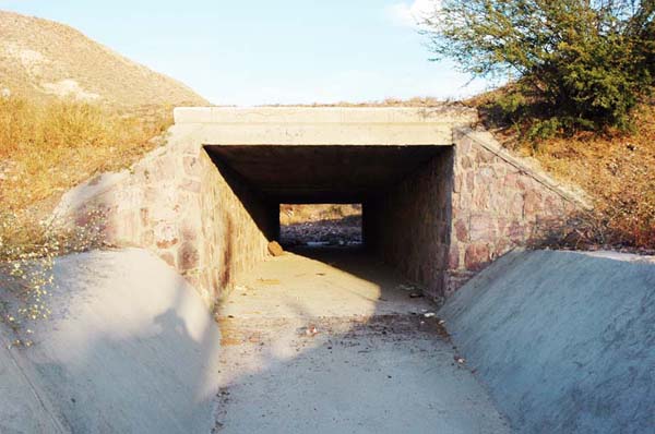
    Fig. 8-10  Typical culvert underpass.

  2. Design a circular concrete culvert with the following data:  Q = 500 cfs; inlet invert elevation z1 = 100 ft; tailwater depth y2 = 4 ft; barrel slope So = 0.01; barrel length L = 200 ft; Manning's n = 0.013; roadway shoulder elevation Er = 115 ft; upstream freeboard Fb = 2 ft. The entrance type is square edge with headwalls. Use ONLINECHANNEL 06 to calculate normal depth and ONLINECHANNEL 07 to calculate critical depth in the culvert. Verify the culvert design using ONLINECULVERT.


REFERENCES

   [Top]   [Culverts]   [Inlet Control]   [Outlet Control]   [Culvert Design]   [Questions]   [Problems]  

Chow, V. T. 1959. Open-channel Hydraulics. McGraw Hill, New York.

U.S. Army Corps of Engineers. 2014. HEC-RAS River Analysis System. Version 4.1, Hydrologic Engineering Center, Davis, California.


http://openchannelhydraulics.sdsu.edu
140905 21:30

Documents in Portable Document Format (PDF) require Adobe Acrobat Reader 5.0 or higher to view; download Adobe Acrobat Reader.