CIVE 530 - OPEN-CHANNEL HYDRAULICS

LECTURE 7A: DESIGN OF CHANNELS FOR UNIFORM FLOW I

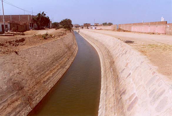
7.1  NONERODIBLE (LINED) CHANNELS

  • Lined channels can withstand erosion, and are considered nonerodible.

  • In designing nonerodible channels, the following considerations are taken into account:

    • Use of a uniform flow formula

    • Hydraulic efficiency

    • Practicality

    • Economy


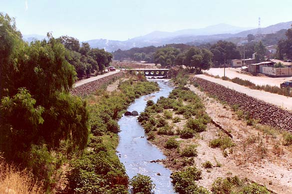
    Tecate Creek, Baja California, Mexico.

  • In designing nonerodible channels, the following factors are taken into account:

    • Kind of material forming the channel body, which determines the roughness.

    • Minimum permissible velocity, to avoid sediment deposition.

    • Channel bottom slope.

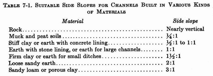
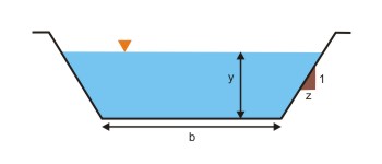
    • Channel side slopes.
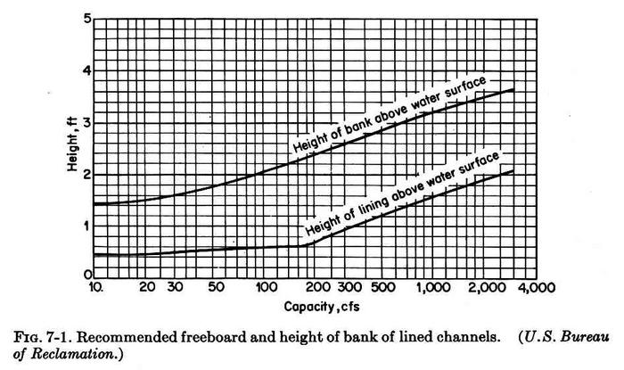
    • Freeboard.

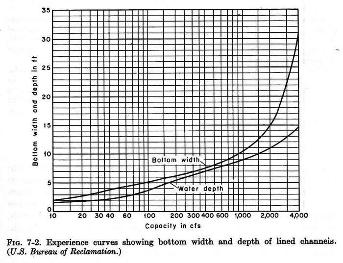
    • The most efficient section.

7.2  NONERODIBLE MATERIAL

  • The nonerodible materials can be:

    • Concrete

    • Stone masonry

    • Steel

    • Cast iron

    • Timber

    • Glass

    • Plastic


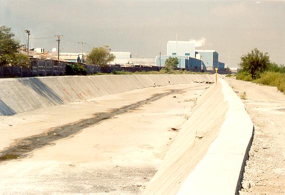
    Rio Santa Catarina, Monterrey, Nuevo Leon, Mexico.

7.3  MINIMUM PERMISSIBLE VELOCITY

  • The minimum permissible velocity, or the nonsilting/nonsettling velocity, is the minimum velocity below which sedimentation will start and aquatic plants will grow.

  • This velocity is uncertain.

  • All water carries a certain amount of sediment (fresh water has typical values of 200 ppm).

  • A velocity of 2-3 fps (0.6-0.9 m/s) may be used safely when the percentage of sediment present in the channel is small (normal case).

  • A minimum velocity of 2.5 fps (0.75 m/s) will prevent the growth of vegetation.

  • Flows with Froude number less than 0.08 need to be checked to assure lack of sedimentation of sands.
7.4  CHANNEL SLOPES

  • In flat terrain, the longitudinal slope of a channel is governed by the topography.

  • The actual design slope may depend on the purpose of the channel.


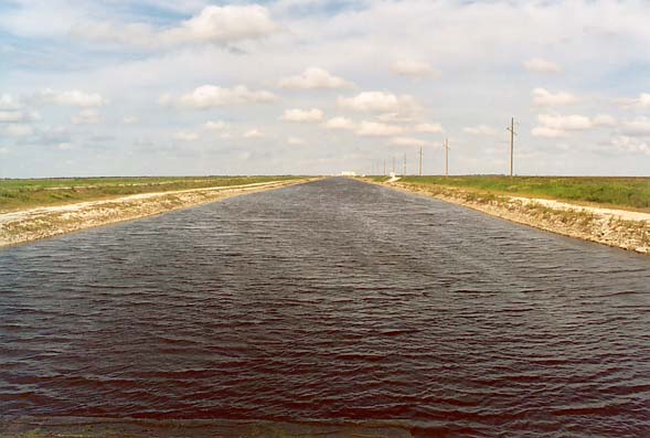
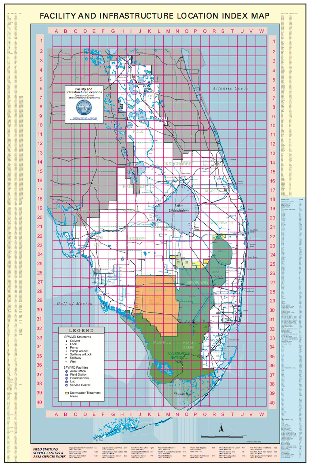
    G-370 Canal, South Florida.


    Facility and infrastructure location map, South Florida Water Management District.

  • For example, channels used for irrigation and hydropower require small slopes, in order not to lose too much head during water transport.

  • Side slopes depend on the kind of material.


Table 7-1 (Chow)

  • Other factors to be considered in determining slopes are:

    • The method of construction.

    • Possible seepage loss.

    • Channel size.

  • Side slopes should be as steep as practicable.

  • For lined canals, USBR uses 1.5:1 (H:V).

    Taymi Canal, Chiclayo, Peru.
7.5  FREEBOARD

  • Freeboard is the vertical distance from the top of the channel to the water surface at the design condition.

  • Distance should be sufficient to prevent waves or fluctuations in water surface from overflowing the sides.

  • There is no universally accepted rule for the determination of freeboard.

  • Wind movement and tidal action may induce high waves.

  • Freeboards varying from less than 5 percent to more than 30 percent of the flow depth are common.

  • Some design criteria (NRCS) allow for the use of all or part of the freeboard to accomodate the PMF (PMP).

  • For semicircular flumes carrying water at velocities less than 80 percent of the critical velocity, and a maximum of 8 fps, use 6 percent of the flume diameter.

  • Design of freeboard is governed by the following considerations:

    • Canal size and location.

    • Storm-water inflow.

    • Water table fluctuations caused by wind action and soil characteristics.

  • USBR practice: 1 ft for small lateral canals with shallow depths, to 4 ft in canals up to 3000 cfs or more.

    Fb = (C y)1/2

    Fb = freeboard (ft)

    y = flow depth (ft)

    C = coefficient (C = 1.5 for Q = 20 cfs; C = 2.5 for Q > 3000 cfs).

  • Freeboard and height of lining are given in Fig. 7-1.


Fig. 7-1 (Chow)
7.6  BEST HYDRAULIC SECTION

  • The channel section that has the least wetted perimeter for a given area has the maximum conveyance.

  • This section is known as the best hydraulic section.

  • The best hydraulic circular section is the semicircle.

  • The best hydraulic trapezoidal section is one-half of a hexagon.

7.7 DETERMINATION OF SECTION DIMENSIONS

  • The determination of the dimensions of the channel cross section includes the following steps:

    • Estimate Manning's n.

    • Select slope S.

    • Select design discharge Q (from the hydrology).

    • Assume bottom width b and side slope z:1 (H:V).

    • Compute normal depth yn and velocity vn using the ONLINECHANNEL01 program.

    • For reasons of practicality, a trapezoidal section is commonly adopted.

    • USBR experience curves, based on discharge: Fig. 7-2.

    • Check to make sure that the normal velocity is above the minimum permissible velocity, to avoid silting (F ≥ 0.08).

    • Add an appropriate freeboard.


Fig. 7-2 (Chow)

Example 7.2.- Design a channel with Q= 400 cfs; b = 20 ft; z = 2; S = 0.0016; n = 0.025.

Use ONLINECHANNEL01 :

yn = 3.36 ft.

vn = 4.45 fps.

Assume freeboard Fb = 2 ft.

Total depth = 3.36 + 2.00 = 5.36 ft.

The velocity is greater than 3 fps. It will not silt.

The Froude number is:

F = V/(gyn)1/2 = 4.45 / (32.17 × 3.36)1/2 = 0.428

Note that in ONLINECHANNEL01, the Froude number is properly defined as:
F = V/(gD)1/2 = 0.479

The Froude number is greater than 0.08. OK to avoid silting.

7.8  DESIGN OF STABLE CHANNELS (ERODIBLE BOUNDARY)

  • The uniform flow formula is by itself not suited for the design of erodible channels.

  • The stability of the channel boundary is dependent on the properties of the material, rather than on the hydraulics of the flow.

  • Two methods are used:

    • Permissible velocity

    • Permissible tractive force
7.9  MAXIMUM PERMISSIBLE VELOCITY


  • The maximum permissible velocity is the greatest mean velocity that will not cause erosion of the channel body.

  • The velocity is estimated from experience.

  • Old channels will stand much higher velocities than new channels because the old channel is stabilized with the deposition of colloidal matter.

  • When other conditions are the same, a deeper channel will convey water with a higher velocity without erosion.

  • This is because for the same mean velocity, the bottom velocities are greater in the shallower channel.

Table 7-3 (Chow)

  • A Russian magazine published values of permissible velocities: Figs. 7-3, 7-4, and 7-5

Fig. 7-3 (Chow)


Fig. 7-4 (Chow)


Fig. 7-5 (Chow)

  • For sinuous channels, the velocities should be lowered in order to reduce scour.

  • Lane suggested a reduction of 5% for slightly sinuous canals, 13% for moderately sinuous, and 22% for very sinuous.

7.10  METHOD OF PERMISSIBLE VELOCITY


  • The design procedure for the method of maximum permissible velocity has the following steps:

    • Given discharge Q and slope S.

    • Estimate Manning's n.

    • Choose side slope z (Table 7-1).

    • Estimate Vmax.

    • Estimate bottom width b.

    • Use ONLINECHANNEL01 to calculate the normal depth and velocity.

    • If vn > Vmax, increase width b.

    • If vn < Vmax, decrease width b.

Example 7.3.- Design a channel with Q= 400 cfs; z = 2; S = 0.0016; n = 0.025; Vmax = 4.5 fps.

Use ONLINECHANNEL01 program.

Using trial and error, for b = 18.7 ft:

yn = 3.47 ft.

vn = 4.496 fps < 4.5 fps.


Go to Chapter 7B.

 
080303