|
|
|
|
|

|
|
|
|
|
|
|
|
|
|
|
|
|
|
|
|
|
|
|

|
|
|

|
|
Table 1. Classification
of vegetative cover depending on degree of retardance.
| Retardance Class | Cover | Condition | C Value | A | Weeping lovegrass | Excellent stand, tall, avg. | 15.8 | Yellow bluestem Ischawmum | Excellent stand, tall, avg. | B | Kudzu | Very dense growth, uncut | 23.0 | Bermuda grass | Good Stand, tall, avg. | Native grass mixture (mixture of bluestems) | Good stand, unmowed | Weeping lovegrass | Good stand, tall,avg. | Lespedeza sericea | Good stand, not woody, tall, avg. | Alfalfa | Good stand, uncut, avg. | Weeping lovegrass | Good stand, unmoved, avg. | Kudzu | Dense growth, uncut | Blue gramma | Good stand, uncut, avg. | C | Crabgrass | Fair stand, uncut, avg. | 30.2 | Bermuda grass | Good stand mowed, avg. | Common lespedeza | Good stand, uncut, avg. | Grass-legume summer mixture | Good stand, uncut, avg. | Centipedegrass | Very dense cover, avg. | Kentucky bluegrass | Good stand, headed, avg. | D | Bermuda grass | Good stand | 34.6 | Common lespedeza | Excellent stand, uncut, avg. | Buffalo grass | Good stand, uncut, avg. | Grass-legume fall mixture | Good stand, uncut 10 to 13 cm | Lespedeza sericea | Cut to 5-cm height | E | Bermuda grass | Good stand, cut to 4cm | 37.7 | Bermuda grass | Burned stubble
| | |||
|
| Table 2. Values of Manning's n for selected lining materials | |
| Concrete: Trowel finish | 0.012-0.014 |
| Concrete: Float finish | 0.013-0.017 |
| Gunite | 0.016-0.022 |
| Flagstone | 0.020-0.025 |
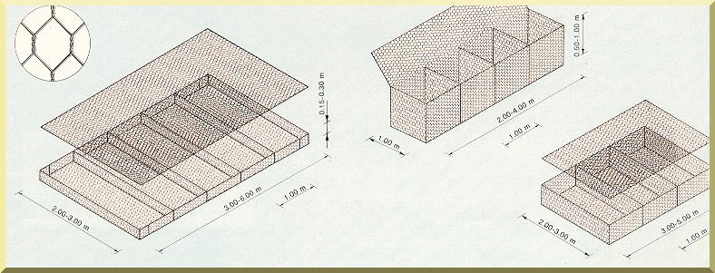
| Gabions | 0.025-0.030 |
| Riprap | 0.040-0.070 |
|
|
|
|
|
|
|
|
|
|
|
|
|
|
|
|
|
|
|
|
|
|
|
Table 3. Arroyo Alamar flood discharges calculated
using mathematical
modeling.
|
||
|
Return period (yr) |
Flood discharge Q (m3/s) |
|
| 2 | 280 | |
| 5 | 530 | |
| 10 | 680 | |
| 25 | 930 | |
| 50 | 1,140 | |
| 100 | 1,310 | |
| 200 | 1,420 | |
| 500 | 1,600 | |
| 1,000 | 1,720 | |
|
|
|
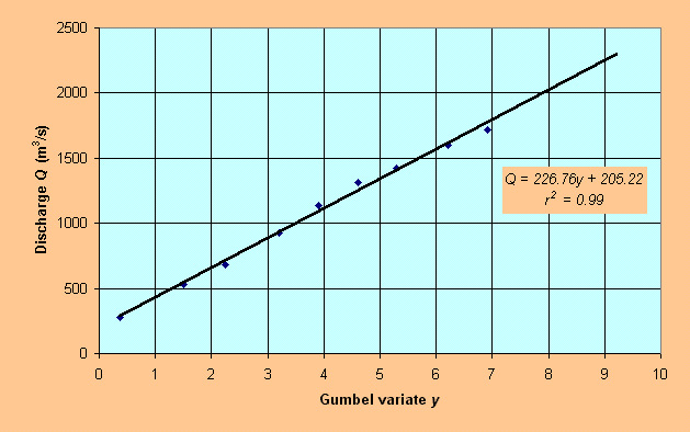
Table 4. Estimated discharges
using the Gumbel method.
|
||
|
Return period (yr) |
Gumbel variate y |
Flood discharge Q (m3/s) |
| 5,000 | 8.52 | 2,140 |
| 10,000 | 9.21 | 2,290 |
|
|
|
|
|
|

|
|
|
|
|
| Table 5. Manning's n values recommended by HEC-RAS for natural streams. | |||
| Type of channel and description |
Minimum
|
Normal
|
Maximum
|
| 1. Main channels | |||
a. Clean, straight, full stage, no rifts or deep pools |
0.025
|
0.030
|
0.033
|
b. Same as above, but more stones and weeds |
0.030
|
0.035
|
0.040
|
c. Clean, winding, some pools and shoals |
0.033
|
0.040
|
0.045
|
d. Same as above, but some weeds and stones |
0.035
|
0.045
|
0.050
|
e. Same as above, lower stages, more ineffective slopes and sections |
0.040
|
0.048
|
0.055
|
f. Same as "d" but more stones |
0.045
|
0.050
|
0.060
|
g. Sluggish reaches, weedy, deep pools |
0.050
|
0.070
|
0.080
|
h. Very weedy reaches, deep pools, or floodways with heavy stands of timber and brush |
0.070
|
0.100
|
0.150
|
| 2. Flood Plains | |||
| a. Pasture no brush | |||
1. Short grass |
0.025
|
0.030
|
0.035
|
2. High grass |
0.030
|
0.035
|
0.050
|
| b. Cultivated areas | |||
1. No crop |
0.020
|
0.030
|
0.040
|
2. Mature row crops |
0.025
|
0.035
|
0.045
|
3. Mature field crops |
0.030
|
0.040
|
0.050
|
| c. Brush | |||
1. Scattered brush, heavy weeds |
0.035
|
0.050
|
0.070
|
2. Light brush and trees, in winter |
0.035
|
0.050
|
0.060
|
3. Light brush and trees, in summer |
0.040
|
0.060
|
0.080
|
4. Medium dense brush, in winter |
0.045
|
0.070
|
0.110
|
5. Medium dense brush, in summer |
0.070
|
0.100
|
0.160
|
| d. Trees | |||
1. Cleared land with tree stumps, no sprouts |
0.030
|
0.040
|
0.050
|
2. Same as above but heavy sprouts |
0.050
|
0.060
|
0.080
|
3. Heavy stand of timber, few down trees, little |
0.080
|
0.100
|
0.120
|
4. Same as above but with flood stage reaching |
0.100
|
0.120
|
0.160
|
5. Dense willows, summer straight |
0.110
|
0.150
|
0.200
|
| 3. Mountain streams, no vegetation in channel, banks usually
steep, with trees and brush on bank submerged |
|||
a. Bottom: gravels, cobbles, and few boulders |
0.030
|
0.040
|
0.050
|
b. Bottom: cobbles with large boulders |
0.040
|
0.050
|
0.070
|
|
|
Table 6. HEC-RAS results
showing flow depths, mean velocities, Froude numbers, and freeboard for corresponding return periods.
|
||||||
| Return period (yr) |
Discharge (m3/s) |
Flow depth (m) | Inbank flow mean velocity (m/s) | Overbank flow mean velocity (m/s) | Froude number | Freeboard (m) |
| - | 550 | 3.278 | 3.60 | - | 0.68 | 0.522 |
| 10 | 680 | 3.706 | 3.87 | - | 0.69 | 0.094 |
| 50 | 1140 | 4.810 | 4.70 | 0.77 | 0.72 | 2.190 |
| 100 | 1310 | 5.147 | 4.62 | 1.18 | 0.73 | 1.873 |
| 500 | 1600 | 5.677 | 5.31 | 1.17 | 0.75 | 1.323 |
| 1000 | 1720 | 5.883 | 5.45 | 1.25 | 0.75 | 1.117 |
| 5000 | 2140 | 6.554 | 5.90 | 1.49 | 0.77 | 0.450 |
| 10000 | 2290 | 6.779 | 6.04 | 1.56 | 0.77 | 0.221 |
| 040117 |