|
[Flood hydrology] |
TOPOLOGY
RAINFLO© has a unique topological structure capable of accomodating a stream network of any order. The basin of interest is divided into a number of individual subbasins, herein referred to as "watersheds." The latter can be of two types: (1) upland watersheds, and (2) reach watersheds.
The number of upland watersheds is U, and the number of reach watersheds is R. Topological rules require that:
U = (R + 1)/2
Likewise:
R = 2U - 1
The total number of watersheds is:
T = U + R
or, else:
T = 3U - 1
A reach juncture is the union of two reach watersheds. The number of reach junctures is:
J = U - 1
The minimum configuration is U = 1, R = 1, T = 2, and J = 0. Table 1 shows valid sets of U, R, T, and J, from U = 1 to U = 10.
| Table 1. Series of U, R, T and J. | |||
| (1) | (2) | (3) | (4) |
| Number of upland watersheds |
Number of reach watersheds |
Total number of watersheds |
Number of reach junctures |
| U | R = 2U - 1 | T = 3U - 1 | J = U - 1 |
| 1 | 1 | 2 | 0 |
| 2 | 3 | 5 | 1 |
| 3 | 5 | 8 | 2 |
| 4 | 7 | 11 | 3 |
| 5 | 9 | 14 | 4 |
| 6 | 11 | 17 | 5 |
Reach watersheds
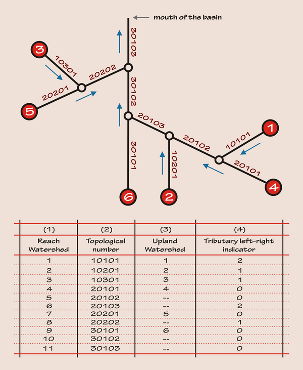
Reach watersheds are numbered consecutively, from 1 to R, in order of increasing five-digit order-branch-reach topological number; see, for instance, Cols. 1 and 2 of Fig. 1, respectively.
To determine the set of topological numbers, assume that the order of the highest-order branch (main stem) is N. Branches contributing to order N branches are of order (N - 1); branches contributing to order (N - 1) branches are of order (N - 2), and so forth. By definition, the branch of lowest order is of order 1, and all the other branches are of respectively higher order (2, 3, ..., up to N).
Each branch has a consecutive number, from upstream to downstream; for example, the [middle] 01 in 20102 in Fig. 1. Each numbered branch has one or more consecutively numbered reaches, from upstream to downstream; for example, the [right] 03 in 20103 in Fig. 1.
Upland watersheds
Upland watersheds are located immediately upstream of reach watersheds with reach 01; for example, upland watershed 5 and reach watershed 20201 in Fig. 1. Upland watersheds are numbered consecutively, from 1 to U, in order of increasing topological number of the neighboring reach watershed; see, for instance, Col. 3 of Fig. 1.
Tributary left-right indicators
The tributary left-right indicators specify whether the tributary branch is located to the left or to the right of its next-higher-order branch, when viewed from upstream to downstream. A left tributary is specified as 1, a right tributary is specified as 2, and the receiving branch is specified as 0. The number of nonzero tributary left-right indicators is equal to the number of reach junctures (J in Table 1); see, for instance, Col. 4 of Fig. 1. Also:
J = U - 1
and:
R = U + J
|
Fig. 1 Example of RAINFLO© topology, with R = 11, U = 6, and J = 5.
An upland watershed generates [its own] local runoff and exports it to its reach watershed; for instance, upland watershed 3 to reach watershed 10301 in Fig. 1. A reach watershed generates [its own] local runoff and routes imported runoff originating in [all] the watersheds located upstream of it toward the mouth of the basin.
The topology works as the brain of the model, enabling hydrograph generation in upland and reach watersheds, routing of hydrographs through reach watersheds, and combination of hydrographs at [reach] junctures. All of these steps are executed in time and space, in an upstream to downstream direction, in an automatic and seamless fashion.