The Lane relation revisited,

with online calculation


Victor M. Ponce


26 February 2015


ABSTRACT

A new Lane relation of fluvial hydraulics is derived from basic principles of sediment transport. It is expressed as follows:

Qs (ds/R)1/3 γ Qw So

Unlike the original Lane relation, this new relation is dimensionless. An online calculator is developed to solve the sediment transport equation arising from the new Lane relation.


1.  INTRODUCTION

This article revisits the Lane relation of fluvial hydraulics (Lane, 1955):

Qs ds Qw So (1)

The new relation is derived from theory and expressed as a dimensionless equation, with the particle size (ds) replaced by the relative roughness function (ds/R)1/3. The derivation follows.


2.  THE FRICTION FUNCTION

The quadratic friction law is (Ponce and Simons, 1977):

τo = ρ f v2 (2)

in which f is a friction factor equal to 1/8 of the Darcy-Weisbach friction factor.

The bottom shear stress in terms of hydraulic variables is (Chow, 1959):

τo = γ R So (3)

Combining Eqs 2 and 3:

So = f v2 / (gR) (4)

The Froude number is (Chow, 1959):

F = v / (gD)1/2 (5)

Combining Eqs. 4 and 5:

So = f (D/R) F2 (6)

For a hydraulically wide channel: D ≅ R. Therefore:

So = f F2 (7)


3.  THE SEDIMENT TRANSPORT FUNCTION

A general sediment transport function is (Ponce, 1988):

qs = ρ k1 vm (8)

According to Colby (1964), the exponent m varies in the range 3 ≤ m ≤ 7, with the lower values corresponding to high discharges, and the higher values to low discharges.

Assume m = 3 as a first approximation (high water and sediment discharge). In this case, the sediment transport function is:

qs = ρ k1 v3 (9)

where k1 is a dimensionless constant.

Using Eq. 2:

qs = (k1/f) τo v (10)

from which:

qs ∝ τo v (11)

i.e., the sediment transport rate, per unit of channel width, is proportional to the stream power τov, as documented by Simons and Richardson (1966) in connection with the prediction of forms of bed roughness in alluvial channels.

The unit-width discharge is:

q = v d (12)

The sediment concentration is:

Cs = qs/(γq) (13)

Combining Eqs. 9 and 12:

Cs = k1 v2/(gd) (14)

For a hydraulically wide channel, d ≅ D. Combining Eqs. 5 and 14, the sediment concentration is:

Cs = k1 F2 (15)

Combining Eqs. 7 and 15:

Cs = k1 (So/f) (16)

The relationship between f and Manning's n is, in SI units (Chow, 1959):

f = gn2 / R1/3 (17)

In U.S. Customary units:

f = gn2 / (1.4862 R1/3) (18)

Thus, in general:

f = k2 n2 / R1/3 (19)

In SI units:

k2 = g = 9.81 (20)

In U.S. Customary units:

k2 = g/1.4862 = 32.17 / 2.208 = 14.568 (21)


4.  THE STRICKLER RELATION

The Strickler relation between Manning n and mean particle size d50 is (Chow, 1959):

n = k3 d501/6 (22)

In SI units:

k3 = 0.04169 (23)

with d50 in meters.

In U.S. Customary units:

k3 = 0.0342 (24)

with d50 in feet.

Assume ds = d50:

n = k3 ds1/6 (25)

n2 = k32 ds1/3 (26)

Combining Eqs. 19 and 26:

f = k2 k32 (ds/R)1/3 (27)


5.  THE SEDIMENT CONCENTRATION

The sediment concentration is:

Cs = k1 (So/f) (16)

Substituting Eq. 27 on Eq. 16:

Cs = k1 So/[k2 k32 (ds/R)1/3] (28)

Thus:

Cs = [k1/(k2 k32)] [So/(ds/R)1/3] (29)

Therefore:

Qs/(γQw) = [k1/(k2 k32)] [So/(ds/R)1/3] (30)

and:

Qs (ds/R)1/3 = [k1/(k2 k32)] γ Qw So (31)


6.  THE MODIFIED LANE RELATION

The Lane relation (Lane, 1955) is:

Qs ds Qw So (1)

Following Eq. 31, the Modified Lane relation is:

Qs (ds/R)1/3 γ Qw So (32)

The sediment transport relation is:

Qs = [k1/(k2 k32)] γ Qw So (R/ds)1/3 (33)

In SI units:

Qs = [k1/(9.81 × 0.041692)] γ Qw So (R/ds)1/3 (34)

Qs = 58.7 k1 γ Qw So (R/ds)1/3 (35)

In U.S. Customary units:

Qs = [k1/(14.568 × 0.03422)] γ Qw So (R/ds)1/3 (36)

Qs = 58.7 k1 γ Qw So (R/ds)1/3 (37)

The sediment transport function is dimensionless; therefore, independent of the system of units.

The sediment transport parameter k1 is the only one to be determined by calibration. Experience shows that this parameter varies typically in the range 0.001 ≤ k1 ≤ 0.01.


7.  APPLICATIONS

Assume pre- and post-development cases, with subscripts 1 and 2, respectively. Further define:

a = Qs2/Qs1 (38)

b = ds2/ds1 (39)

c = R2/R1 (40)

d = Qw2/Qw1 (41)

e = So2/So1 (42)

From the modified Lane relation (Eq. 32):

a (b/c)1/3 = d e (43)

Thus, the channel slope change is:
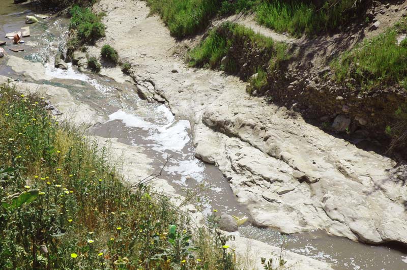
e = (a/d) (b/c)1/3 (44)

Example 1

A river reach entering a reservoir, with a = 0.95, b = 0.95, c = 5., and d = 1., will result in e = 0.55 (aggradation in the reservoir) (Fig. 1).

Sediment deposition at tail of reservoir

Fig. 1   Sediment deposition at tail of reservoir.

Example 2

A river reach downstream of a sediment retention basin, with a = 0.3, and b = 1., c = 0.95, and d = 0.9, will result in e = 0.34 (degradation). In practice, the latter may be limited by geologic controls (armoring or bedrock) (Fig. 1).

Sediment deposition at tail of reservoir

Fig. 2   Erosion to bedrock downstream of sediment retention dam.


8.  ONLINE CALCULATOR

Given: Water discharge Qw = 100 m3/s; bottom slope So = 0.001; hydraulics radius R = 2 m; particle size ss= 1 mm. Use default k = 0.001. Use onlinemodifiedlane.php to calculate sediment discharge.

Result of the online calculator: Sediment discharge Qs = 6,389.9 M.Tons/day.


9.  EXTENSION TO m > 3

In the general case for the exponent of the sediment transport function, i.e., for m > 3, Eq. 8 remains:

qs = ρ k1 vm (8)

The general Modified Lane relation is:

Qs (ds/R)1/3 γ Qw So vm - 3 (45)

The general sediment transport relation is:

Qs = 58.7 k1 γ Qw So (R/ds)1/3 vm - 3 (46)


10.  SUMMARY

A new Lane relation of fluvial hydraulics is derived from basic principles of sediment transport. It is expressed as follows:

Qs (ds/R)1/3 γ Qw So (32)

Unlike the original Lane relation:

Qs ds Qw So (1)

the new relation (Eq. 32) is dimensionless. A sediment transport equation is derived from the modified Lane relation, particularly for the case of sediment rating exponent (Eq. 8) m = 3:

Qs = 58.7 k1 γ Qw So (R/ds)1/3 (35)

An online calculator is developed to solve the sediment transport equation.


REFERENCES

Chow, V. T., 1959. Open-channel hydraulics. Mc-Graw-Hill, New York.

Colby, B. R., 1964. Discharge of sands and mean velocity relations in sand-bed streams. U.S. Geological Survey Professional Paper No. 462-A, Washington, D.C.

Lane, E. W., 1955. The importance of fluvial morphology in hydraulic engineering. Proceedings, American Society of Civil Engineers, No. 745, July.

Ponce, V. M., and D. B. Simons, 1977. Shallow wave propagation in open channel flow. American Society of Civil Engineers Journal of the Hydraulics Division, Vol. 103, No. HY12, December.

Ponce, V. M., 1988. Ultimate sediment concentration. Proceedings, National Conference on Hydraulic Engineering, Colorado Springs, Colorado, August 8-12, 1988, 311-315.

Simons, D. B., and E. V. Richardson, 1966. Resistance to flow in alluvial channels. U.S. Geological Survey Professional Paper 422-J, Washington, D.C.


NOTATION

a, b, c, d, e = ratios of post- and pre-development hydraulic variables;

C = Chezy coefficient;

Cs = sediment concentration;

d = flow depth;

D = hydraulic depth;

ds = particle size;

d50 = mean particle size;

f = friction factor equal to 1/8 of Darcy-Weisbach friction factor;

F = Froude number;

g = gravitational acceleration;

k1 = dimensionless sediment transport parameter;

k2 = friction parameter;

k3 = coefficient in the Strickler relation;

n = Manning's friction coefficient;

q = unit-width water discharge;

qs = unit-width sediment discharge;

Qw = water discharge;

Qs = sediment discharge;

R = hydraulic radius;

So = bottom slope;

v = mean velocity;

γ = unit weight of water;

ρ = density of water; and

τo = bottom shear stress.


Documents in Portable Document Format (PDF) require Adobe Acrobat Reader 5.0 or higher to view;
download Adobe Acrobat Reader
.
201013