|
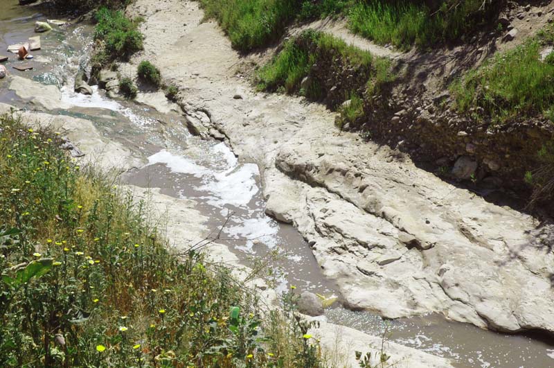
| Fig. 1 Erosion to bedrock downstream of sediment retention dam. |
Victor M. Ponce
Professor of Civil Engineering
San Diego State University
[110807]
INTRODUCTION
This article revisits the Lane relation of fluvial hydraulics (Lane, 1955):
| Qs ds ∝ Qw So | (1) |
in which Qs = solid discharge; Qw = liquid discharge; ds = mean particle size; y So = slope of the stream or river.
The new relation is derived from theory, and expressed as a dimensionless equation, with the particle size (ds) replaced by the relative roughness function (ds/R)1/3.
| Qs (ds /R )1/3 ∝ γ Qw So | (2) |
The derivation follows.
THE FRICTION FUNCTION
The quadratic friction law is (Ponce and Simons, 1977):
| τo = ρ f v 2 | (3) |
in which τo = bottom shear stress; ρ = density of water; f = friction factor, equal to 1/8 of the Darcy-Weisbach friction factor, and v = mean velocity.
The bottom shear stress in terms of hydraulic variables is (Chow, 1959):
| τo = γ R So | (4) |
in which γ = unit weight of water; and R = hydraulic radius.
Combining Eqs. 3 and 4:
| So = f v 2 / (gR) | (5) |
The Froude number is (Chow, 1959):
| F = v / (gD)1/2 | (6) |
in which D = hydraulic depth (D = A /T ),
in which A = flow area;
T = top width, and
Combining Eqs. 5 and 6:
| So = f (D/R) F 2 | (7) |
For a hydraulically wide channel: D ≅ R. Therefore:
| So = f F 2 | (8) |
Equation 8 establishes the proportionality between gravity (So) and friction (f ).
THE SEDIMENT TRANSPORT FUNCTION
A general sediment transport function is (Ponce, 1988):
| qs = ρ k1 v m | (9) |
in which qs =
solid discharge, per unit of channel width; ρ = density of water;
According to Colby (1964), the exponent m varies in the range 3 ≤ m ≤ 7, with the lower values corresponding to high discharges, and the higher values to low discharges.
Assume m = 3 as a first approximation (high water and sediment discharge). In this case, the sediment discharge is proportional to the stream power P, in which P = τo v (Simons and Richardson, 1966). Thus, the sediment transport function is:
| qs = ρ k1 v 3 | (10) |
where k1 is a dimensionless constant.
The unit-width discharge is:
| qw = v d | (11) |
The sediment concentration is:
| Cs = qs / (γ qw ) | (12) |
Combining Eqs. 10 and 12:
| Cs = k1 v 2 / (gd ) | (13) |
For a hydraulically wide channel, d ≅ D. Combining Eqs. 6 and 13, the sediment concentration is:
| Cs = k1 F 2 | (14) |
Combining Eqs. 8 and 14:
| Cs = k1 (So / f ) | (15) |
The relationship between f and Manning's n is, in SI units (Chow, 1959):
| f = g n 2 / R 1/3 | (16) |
In U.S. Customary units:
| f = g n 2 / (1.4862 R 1/3) | (17) |
Thus, in general:
| f = k2 n 2 / R 1/3 | (18) |
In SI units:
| k2 = g = 9.81 | (19) |
In U.S. Customary units:
| k2 = g / (1.486)2 = 14.568 | (20) |
THE STRICKLER RELATION
The Strickler relation between Manning n and mean particle size d50 is (Chow, 1959):
| n = k3 d501/6 | (21) |
In SI units:
| k3 = 0.04169 | (22) |
with d50 in meters.
In U.S. Customary units:
| k3 = 0.0342 | (23) |
with d50 in feet.
Assume ds = d50:
| n = k3 ds1/6 | (24) |
| n 2 = k32 ds1/3 | (25) |
Combining Eqs. 18 and 25:
| f = k2 k32 (ds /R )1/3 | (26) |
THE SEDIMENT CONCENTRATION
Substituting Eq. 26 on Eq. 15:
| Cs = k1 So / [k2 k32 (ds /R)1/3 ] | (27) |
Thus, the concentration of sediments is:
| Cs = [k1 /(k2 k32 ) ] [ So / (ds /R )1/3 ] | (28) |
Therefore:
| Qs /(γ Qw ) = [ k1 / (k2 k32 ) ] [ So / (ds /R )1/3 ] | (29) |
and:
| Qs ( ds /R )1/3 = [ k1 / (k2 k32 ) ] γ Qw So | (30) |
THE MODIFIED LANE RELATION
Following Eq. 30, the Modified Lane relation is:
| Qs (ds /R )1/3 ∝ γ Qw So | (31) |
The sediment transport relation is:
| Qs = [k1 / (k2 k32 ) ] γ Qw So (R /ds )1/3 | (32) |
In SI units:
| Qs = [k1 / (9.81 × 0.041692) ] γ Qw So (R /ds )1/3 | (33) |
| Qs = 58.7 k1 γ Qw So (R /ds )1/3 | (34) |
In U.S. Customary units:
| Qs = [k1 / (14.568 × 0.03422) ] γ Qw So (R /ds )1/3 | (35) |
| Qs = 58.7 k1 γ Qw So (R /ds )1/3 | (36) |
Equations 34 and 36 are the same; therefore, the coefficient 58.7 and the sediment transport function are independent of the system of units.
The sediment transport parameter k1 is valid only for m = 3 (Equation 8), and it is the only one to be determined by calibration. Experience shows that this parameter varies typically in the range 0.005 ≤ k1 ≤ 0.02.
APPLICATIONS
Assume pre- and post-development cases, with subscripts 1 and 2, respectively. Further define:
| a = Qs2 /Qs1 | (37) |
| b = ds2 / ds1 | (38) |
| c = R2 / R1 | (39) |
| d = Qw2 / Qw1 | (40) |
| e = So2 / So1 | (41) |
From the modified Lane relation (Eq. 31):
| a (b/c)1/3 = d e | (42) |
Thus, the slope change is:
| e = (a/d) (b/c)1/3 | (43) |
Example 1
A river reach downstream of a channel diversion intake, with a = 0.99, b = 1, and c = 0.95, and d = 0.9, will result in e = 1.12 (aggradation).
Example 2
A river reach downstream of a sediment retention basin, with a = 0.3, b = 1., c = 0.95, and d = 0.9, will result in e = 0.34 (degradation). In practice, the latter may be limited by geologic controls (armoring or bedrock) (Fig. 1).
REFERENCES
Chow, V. T., 1959. Open-channel hydraulics. Mc-Graw-Hill, New York.
Colby, B. R., 1964. Discharge of sands and mean velocity relations in sand-bed streams. U.S. Geological Survey Professional Paper No. 462-A, Washington, D.C.
Lane, E. W., 1955. The importance of fluvial morphology in hydraulic engineering. Proceedings, American Society of Civil Engineers, No. 745, July.
Ponce, V. M., and D. B. Simons, 1977. Shallow wave propagation in open channel flow. American Society of Civil Engineers Journal of the Hydraulics Division, Vol. 103, No. HY12, December.
Ponce, V. M., 1988. Ultimate sediment concentration. Proceedings, National Conference on Hydraulic Engineering, Colorado Springs, Colorado, August 8-12, 1988, 311-315.
Simons, D. B., and E. V. Richardson. 1966. Resistance to flow in alluvial channels. U.S. Geological Survey Professional Paper 422-J.
NOTATION
a, b, c, d, e = ratios of post- and pre-development hydraulic variables, Eqs. 37 to 41;
C = Chezy coefficient;
Cs = sediment concentration;
d = flow depth;
D = hydraulic depth;
ds = particle size;
d50 = mean particle size;
f = friction factor equal to 1/8 of Darcy-Weisbach friction factor;
F = Froude number;
g = gravitational acceleration;
k1 = dimensionless sediment transport parameter;
k2 = friction parameter;
k3 = coefficient in the Strickler relation;
n = Manning's friction coefficient;
P = stream power;
q = unit-width water discharge;
qs = unit-width sediment discharge;
Qs = sediment discharge;
Qw = water discharge;
R = hydraulic radius;
So = bottom slope;
v = mean velocity;
γ = unit weight of water;
ρ = density of water; and
τo = bottom shear stress.
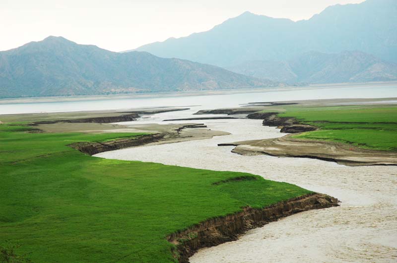 |
| Fig. 2 Sediment deposition at tail of reservoir. |