|
TUNNEL BORING
Jerod Coleman, Jesse Owens, Matt Maechler |

|
|
What is tunnel boring? The bore construction method for tunnels involves digging a tube-like passage through the earth. This usually refers to mountain tunneling, however it has also been used for tunneling under bodies of water. Rather than conventional tunneling methods which extensively use explosives and manual labor, mechanized tunnel excavation is done by Tunnel Boring Machines (TBM's).

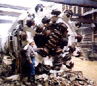
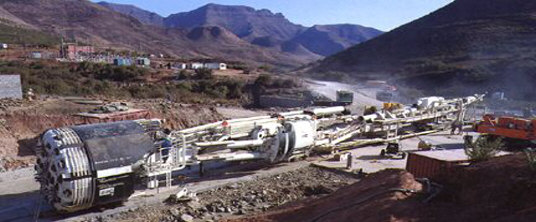
A tunnel boring machine (TBM) consists of a shield (a large metal cylinder) and trailing support mechanisms.
At the front end of the shield a rotating cutting wheel is located. Behind the cutting wheel there is a chamber where, depending on the type of the TBM, the excavated soil is either mixed with slurry (so-called slurry TBM) or left as-is (earth pressure balance or EPB shield). The choice for a certain type of TBM depends on the soil conditions. Systems for removal of the soil (or the soil mixed with slurry) are also present.
Behind the chamber there is a set of hydraulic jacks supported by the finished part of the tunnel which are used to push the TBM forward. Once a certain distance has been excavated (roughly 1.5-2 meters), a new tunnel ring is built using the erector. The erector is a rotating system which picks up pre-cast concrete segments and places them in the desired position.
Behind the shield, inside the finished part of the tunnel, several support mechanisms which are part of the TBM can be found: dirt removal, slurry pipelines if applicable, control rooms, rails for transport of the pre-cast segments, etc.
|
|
|
|
|
|

By the 17th century, tunnels were being constructed for canals. Without roads or railways to transport raw materials from the country to the city, watery highways became the best way to haul freight over great distances.
With trains and cars came a tremendous expansion in tunnel construction. During the 19th and 20th centuries, the development of railroad and motor vehicle transportation led to bigger, better, and longer tunnels.
Today, not even mountains and oceans stand in the way. With the latest tunnel construction technology, engineers can bore through mountains, under rivers, and beneath bustling cities. Before carving a tunnel, engineers investigate ground conditions by analyzing soil and rock samples and drilling test holes.
The first successful tunneling shield was developed by Sir Marc Isambard Brunel to excavate the Thames Tunnel beginning in 1825 (though the tunnel would not be opened until 1843). Brunel is said to have been inspired in his design by the shell of the shipworm, whose efficiency at boring through submerged timber he observed while working in a shipyard.
Brunel's original design was substantially improved by Peter W. Barlow in the course of the construction of the Tower Subway under the River Thames in central London in 1870. Probably the most crucial innovation of Barlow's design was that it had a circular cross-section (unlike Brunel's, which was of rectangular cross-section), which at once made it simpler in construction and better able to support the weight of the surrounding soil.
The Barlow design was enlarged and further improved by James Henry Greathead for the construction of the City and South London Railway (today part of London Underground's Northern Line) in 1884. To this day, most tunneling shields are still loosely based on the Greathead shield.
|
|


|
|
Mechanized tunneling
The advantages are:
1. Minimal ground disturbances
2. Minimal support requirements
3. Higher advance rates
4. Continuous mining, non-cyclical
5. Improved safety. There are no explosives, and reduces chances of rocks falling on workers' heads.
The disadvantages are:
1. It is expensive
2. Hard, abrasive rock causes problems for cutters
3. It is difficult for the machines to cut through weathered, sheared, and highly jointed rock
4. Actual tunneling time is reduced by frequent break-downs. A TBM is usually tunneling a maximum of 50% of the time. Reduced active tunneling time is also due to problems that come from back-up services, ground conditions and needing to change cutters. As well, there needs to be time for hoisting muck, fixing electrical problems and dealing with water inflow and blockages.
Conventional Methods
The advantages are:
1. Tunnels can easily be designed in any shape the designer wants. By conventional tunneling, it is easier to make a flat floor where a track can be put in (to cart out muck). With a TBM, the floors must be filled with cement to be made flat. This takes time and money.
2. It is cheaper way to make tunnels. Explosives and laborers do not cost as much as a TBM.
3. Mechanical break-downs are not as prevalent because fewer machines are used.
The disadvantages are:
1. It is dangerous for workers
2. Tunnel walls could not efficiently be made smooth
3. It takes longer time to make a tunnel conventionally
|
|
Tunneling for transit projects is as much an art as a science. Variables affecting the design and construction of a project include predicting the behavior of ground mass during construction and the vagaries of ground-water hydrology. Predictive models are only of some use because no two projects are the same. The process of tunnel design and construction involves evaluation of geologic conditions, identifying and acquiring the appropriate tunnel boring equipment, ground modification techniques, environmental impact mitigation, utility and traffic protection, contractor selection and payment, and risk management. Research is needed in all of these areas.
Preliminary Geotechnical Investigations are needed to identify critical engineering and geotechnical issues, define design information needs, assess overall project feasibility, and provide preliminary cost estimates. Engineers typically utilize probabilistic methods to define the range, and uncertainty, in project designs and related cost estimates at this preliminary stage.
Design and Implementation of Site Investigation Programs are needed for new tunnels. These include:
1. Site reconnaissance and mapping
2. Layout and supervision of exploration plans
3. Identification of laboratory and in-situ testing needs
4. Instrumentation setup and monitoring
Design and Engineering Tasks including:
1. Excavation method selection, including risk-based modeling of excavation system performance
2. Tunnel Boring, monitoring and optimization
3. Design of ground support and monitoring systems including design with shot Crete, geotechnical instrumentation for support performance verification
4. Seepage estimation and control
5. Subsidence evaluation and monitoring
6. Ventilation system design and surveys
7. Tunnel refurbishment/water proofing design and specification
8. Geotechnical design reports
9. Systems for emergency procedures
Geotechnical Field Services need to be designed for the construction phase. These include:
1. Geologic and geotechnical mapping of excavation
2. Monitoring of geotechnical instrumentation
3. Review of geotechnical data, stability analyses and support design
4. Monitoring of excavation progress with respect to geotechnical conditions
5. Monitoring of support design with respect to conditions encountered
6. Construction management and quality assurance
Methods of Groundwater Control
The methods of groundwater control in tunneling are dewatering, grouting, compressed air, freezing and special construction methods.
Dewatering is the simplest and cheapest method of controlling groundwater by pumping from wells. However, there may be undesirable side effects from consolidation of the soil subject to increased effective weight.
Grouting can be used to control groundwater and at the same time reduce surface settlements. However, it is normally an expensive and time consuming process and is not perfectly reliable even when great care is exercised.
Compressed air is most often used to stabilize the ground in tunnels constructed in permeable soils below the water table, where dewatering is impractical.
Freezing is more commonly used in shaft sinking than in tunneling, but the method is useful where nothing else will work, providing there is access to the ground surface over the alignment of the tunnel.
Lighting
When traveling through roadway tunnels, lighting is a must. The entire length of the tunnel must be well lit in order for the travelers to be able to safely travel through the tunnel. With this in mind, a whole phase of electrical design must be taken into consideration when designing a roadway tunnel.
Emergency Procedures
Tunnel Ventilation Systems
Road and rail tunnels have an established need for ventilation systems for the removal of heat or exhaust fumes from vehicles. In the event of a tunnel fire, these ventilation systems double up as smoke control systems. Tunnel ventilation systems are designed on the principle of providing a critical velocity in order to maintain a smoke-free environment on one side of the fire.
Means of Escape
The provision of refuges and/or escape routes can be costly and difficult. They may increase the section of a tunnel and introduce new engineering challenges. The combination of fire, risk assessment and ventilation must in particular consider and develop solutions which are cost effective and fully justifiable on a rational basis and not just from a perception of horizontal danger.
For financial reasons, the safety guidelines for roadways cannot always be followed. For instance, tunnels do not always have emergency shoulders. Thus, the only escape routes for pedestrians caught in the tunnel are the doorways placed every few hundred yards to connect the two sides of the tunnel.
Stair Pressurization
The use of positive pressurization of spaces is often applied to staircases and escape routes in order to keep them free of smoke. The systems involve the use of high-volume fans and air relief devices that prevent the entry of smoke into these escape routes via doors opening into the fire affected area.
|
|
Several processes need to be considered prior to the construction of a bored tunnel. Some tunnel excavations need to be stabilized in order to install the supports. This typically occurs in "soft ground" below the water table. These conditions can also occur in rock tunnels when the tunnel is advanced through weak zones charged with groundwater. Methods routinely used for stability include: grouting, dewatering, compressed air, placement of freeze pipes beneath the soil, and injection of specialized foams.
Tunneling projects using shielded TBM involve the following activities:

1. Excavation and support of working shafts
2. Excavation and support of undercut and tail tunnel
3. Excavation of the tunnel itself
4. Disposal of soil from tunnel face
5. Hoisting the soil to ground level
6. Lining the tunnel
7. Extending services and rail tracks (if necessary)
8. Excavation and support of the removal shaft
Except for activities (1), (2) and (8) of the above, these are repetitive tasks in a tunnel construction cycle. The purpose of the pre-planning is to ensure that minimum waste occurs during the entire construction process. The goal of eliminating the wait time is to optimize the resources and the construction process. The advancement of the tunneling operation depends on the progress of the tunneling activities between the working shaft and the tunnel face. In order to optimize the tunneling operation, all activities should be coordinated to minimize the delay occurring at either end.
Excavation on long tunnels is typically done with shielded mechanical moles. The shield provides temporary support for the front sections of the tunnel and a safe working area for the crew. There are two types of tunnel boring machines: open-face and closed-face shielded machines. Open face machines are generally employed in competent soils with reasonable stability. In conditions of runny soils such as silt or sand, a closed-face-shielded machine is used. An important property of TBM's is their excavation rate, which is dependent on the soil conditions and the TBM horsepower. Another important property is the stroke length, which determines how often the TBM will need to be re-set.
Soil Disposal
The dirt handling process involves the transportation and disposal of spoil from the tunnel face to the shaft where it is lifted to the surface. Spoil can be hauled horizontally using trains and/or belt conveyors. The selection criterion depends on the tunnel site conditions. Belt conveyers have the advantage of providing a continuous spoil removal system. However, they typically require excessive maintenance. Train haulage is energy efficient and is compatible with most excavating and loading methods and is adaptable to almost all sizes of tunnels. Trains can also be fitted with special cars capable of transporting laborers and support liners. Depending on the tunnel diameter, a single or double-track system can be used. In most cases, a track switching system is utilized at the undercut to allow multiple trains to share a single track. The working shaft is utilized to remove the spoil and to transport the construction materials and personnel. The dirt can be hoisted with a skip, a clamshell bucket, or a gantry crane. Clamshells are typically used in shallow tunnels. In medium depth tunnels (10 m to 20 m), gantries or cranes are more economical and in deep tunnels (>30 m), a cage or skip is used with a head frame for hoisting the muck.
Tunnel Supports
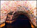
The two major types of tunnel support systems consist of either (1) rib-and-lagging or (2) concrete segments. Rib and lagging method has a record of high performance in a variety of ground conditions. During installation, lagging is wedged circumferentially between rib and soil. The rib and lagging support system acts as the primary lining system for the tunnel. A secondary layer made of cast-in-place concrete is placed when tunneling excavation is finished. Pre-cast concrete segment lining is the alternative to rib-and lagging, which act as both the primary and final lining systems. Each segment is designed as a compact structural unit and thus requires the least amount of handling during erection. The full ring typically consists of four identical segments. It is partially installed inside the shield of the TBM. The ring is expanded tightly against the soil as it leaves the shield. Metal spacers are inserted in the gap created by the ring expansion to maintain its structural integrity. The gap is subsequently filled with concrete and the joints are patched with cement mortar.
Breaking Ground
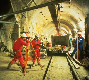
In general construction of a tunnel, contractors will construct shafts (large holes in the ground that provide construction access to the tunnel cavity) at various intervals along the new tunnel route to complete underground work. A specific tunnel boring machine determined through the design will be used to "drill" the tunnel cavity.
The aboveground construction work will take place in and around shaft sites. These shafts will vary in size according to the type of work that will be performed, and will be constructed before excavation of the tunnel cavity begins. For some construction work, the contractor will utilize existing shaft sites, which will help reduce construction time at those sites.
To excavate the tunnel cavity, the tunnel boring machine will be lowered into shafts to "drill" the tunnel and then removed through retrieval shafts at the end of each tunnel route.
Construction trailers, crew parking, trucks, piping materials, generators, a crane, and other equipment will be located onsite. As the machine "drills" forward, all the excavated material will be removed back through the shaft and hauled away by trucks. This removal of spoil is through a process called mucking.
Other shafts will be used to pull the tunnel boring machine out of the ground after it arrives at the end of the route, as well as to make connections between the existing utilities and the new tunnel. These construction sites will not be in operation for the full construction period.
Breakdowns
Due to this method of tunneling, it's the nature of the beast for TBM's to breakdown while in the tunnel. Therefore the swift recovery of the machine is significantly important. The process most likely used in this situation is done by freezing the subsoil and extracting the machine with a crane. This method is effective in tight or low overhead areas, near existing structures, or at vibration-sensitive areas. Batter pipes are directionally bored and placed below the tunnel casing and freeze the groundwater to seal it off. Freezing of soil can be employed quickly to recover machines with little or no dewatering.

|
|
With the economic slowdown the world economy has faced over the last few years, tunneling work seems to have gone, to some degree, against that tide. While work has slowed a bit, projects scheduled for the next few years show activity increasing.
"Tunneling in North America has been slow over the past 18 months, but there's quite a bit of work to bid on over the next two and a half years," Shaw says. "The market is growing quite unbelievably. We've identified projects out to 2010 and don't see a downturn in the industry for at least four to five years."
In fact, for 2004, several TBM contractors have identified more than $3 billion worth of tunneling opportunities and in 2005, others say there is another $3 billion worth of work ("That's huge").
(Overall), we think the market is strong today and will remain strong for the future. Contractors firmly believe, given the large volume of anticipated projects, that they will continue a steady growth in the coming years.
Affholder Inc. is currently working on a $168 million project in Chicago with Jay Dee Contractors, Livonia, Mich., for the Metropolitan Water Reclamation District of Greater Chicago. The two are working on the Little Calumet Leg -- a 7.9-mile, 18-ft diameter tunnel that runs at depths between 150 and 210 ft. This phase is part of the City's $3.8 billion Tunnel and Reservoir Plan (TARP).
Over the years, Affholder Inc. has forged relationships with tunnel boring machine manufacturers such as Lovat Inc. and The Robbins Co., working to develop even more advanced technology. Ideally, Shaw would like to see the technology reach a point where only one TBM is needed to bore through soft ground and rock.
The sky's the limit for the future of tunnel boring. "As long as there is work out there, we're going to try and get our piece of it," says Shaw, who serves as president of Affholder Inc. "We're certainly not greedy and we don't have any aspirations or egos to be the biggest boy on the block. We just want to go about our business. We want to make money and take care of our stockholders and our people."
http://attila.sdsu.edu/~owens/tbmpaper.html
| November 3, 2004 |