Steel Suspension Bay Bridge

Brad Weisbecker, Reyhaneh Dadafshar, and Joe McGhee
San Diego State University
Steel Suspension Bay Bridge
Brad Weisbecker, Reyhaneh Dadafshar, and Joe McGhee
San Diego State University
|
CONTENTS
Appearance |
| Appearance [Back to Top] |
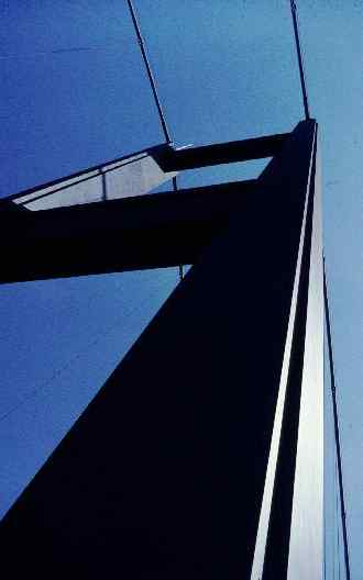
| The natural elegance, of the suspension bridge design, provides both a pleasing appearance, as well as a reassuring feeling that the bridge is safe for travel. Just imagine seeing the bridge's massive cables swooping down from its mighty towers. It is this image that provides travelers with comfort, by allowing them to observe the structural components of the bridge while on the bridge. Furthermore, because of the sleek and simple look to the underbelly of the bridge, observes of the bridge are allowed to see more of the ocean below. This is a nice change from bridge designs which have massive structural components underneath the bridge, such as columns and arches. |
| Materials [Back to Top] |
|
Steel
Steel is made of many materials, all of them alloys of iron with one or more of the other chemicals, and it also includes some carbon. Steels are used because of their high tensile strength, corrosion resistance, good performance at high temperature, and elasticity. Because of the fact that many special steels are expensive, choosing these materials for a large structure such as a bridge has to balance the performance in terms of quantities like strength to weigth ratio against cost. Also, the cost of any material depends on its distribution, location, and the cost of extracting it from the ore or other raw materials. Moreover, steel can be forged and rolled into different shapes ranging from I-beams to wires. The properties of the steel depend strongly on the treatment done before use. For instance, this treatment may include mechanical procedures such as forging, rolling or drawing, or thermal treatments such as quenching and annealing. The treatment is done to improve the performance of the steel. Steel is used in the longest suspension bridges, the longest cable stayed bridges, the longest arch bridges, the longest cantilever bridges, and the longest beams. Concrete There are three main forms of concrete, simple concrete, reinforced concrete, and pre-stressed concrete. Concrete is used in constructions such as private driveways and patios. For anything of more than trivial size, reinforcing bars will be used. Concrete is relatively weak under tension, and this is the important property of the concrete. Therefore, it is poor for making beams. The greatest advantage of using concrete is that it can be poured into molds to take up any required shape, whether it is a huge dam or a small foundation for a shed. Reinforced concrete contains iron bars with ragged surfaces to grasp the concrete. These bars are placed deliberately inside the formwork before any concrete is poured. Performing this reinforcement is very important since it is going to take any tensile forces that arise. Moreover, before the structure is loaded, there is a little stress in the bars, and these bars don't necessarily prevent the concrete from cracking. However, they do prevent the structure from collapsing if cracks do occur. Also, it is clear that if the tensile stress on a reinforced concrete member is enough to stretch the bars to the point where the concrete is stressed to its limit, the concrete will crack. |
| Basic Parts [Back to Top] |
|
Basic Parts for a Suspension Bridge
Gravity: -May not be considered a "part", but it is unavoidable to construct without keeping the weight of the structure itself and the weight of the loads it will support in mind. Struts and Ties: -Strut is always in compression while tie is always in tension. Attachments: -The joints that connect struts, ties and other parts together. Keeping varying and static forces in mind, attachments at joints have to be able to bear loads effectively. Cables: -A tie that is flexible and often the longest piece of the suspension structure. May be divided into segments. Always curved by their own weight. Beams: -Neither struts nor ties. Main function is to rest on two or more supports, providing enough rigidity to remain straight. All beams experience compression and tension simultaneously. Towers: -Required to hold cables high enough to be able to support structure weight and to allow clearance underneath the bridge. Force may vary greatly along its length due to its own weight.
Piers: -Are everything else that holds up the rest of the structure. Often simple vertical beams that sometimes survive disasters that destroy everything else in the structure. |
| Foundations [Back to Top] |
|
The Foundation of a Bridge, the Key to Reliability
Every bridge has to have at least one footing in the ground. These supports have to be placed so as not to move unacceptably. The stresses have to be reduced to what the ground the support lies on can handle. A general rule to determine the size of an excavation to build a foundation is to remove as much weight in soil as the weight of the structure to be supported. Problems with soil: -Differing types of soil -Variations of properties within in the same site -Variations of properties over time (water content, earthquakes, creep, freezing water) Problems with building the foundation: -Depth of poor ground above firm rock -Depth of water above ground -Speed of water flow -Tidal variation in depth of water (especially in a bay) -Scour - Generated by the flow of water past an obstacle, especially when the flow is fast and turbulent. If the scour reaches low enough, the foundation can be seriously threatened. The mere presence of foundations within a water system, such as a river or bay, changes the flow of water. Anchoring the Suspension cables: -If the soil does not allow for suitable anchorage, then one has to be built, usually relying on sheer weight alone.
-Often, of the hundreds or thousands of individual cables used, many or all of them can be fastened to different, individual fixtures within the anchorage.
|
| Basic Structural Rules [Back to Top] |
|
Forces on a Bridge External Forces (Vertical) -Reaction to the weight of the bridge -Weight of traffic -Lift or down-force caused by wind (Longitudinal) -Reaction to thrust of an arch -Reaction to the tension of a suspension bridge -Force generated by traffic, especially accelerating traffic (Transverse) -Wind pressure -Pressure of river or water or tidal water -Forces generated by traffic on a curved bridge Many forces are intermittent or erratic such as turbulence in the air, vibration from live loads, and traffic variations. Forces during construction are drastically different than those of the completed structure. The larger the structure, the more difficult the task of managing external forces becomes. Stresses and Strains Stress is defined as force per unit area, so that comparisons can be made between different structures and different materials in a fair way. Stress can vary continuously throughout a structural member. The stress in a suspension cable varies because the load varies along the length. At the center of the span, the cable only has to resist the horizontal force. Progressing towards the towers, the cable feels more and more force from the weight of the deck and the hangers. When a compressive stress is applied, it shrinks very slightly, because it is being pushed down at the top, and up at the bottom, by the earth. Conversely, if it were pulled at each end it would stretch. Moreover, "elastic" also means that if the stress is removed, the shape returns exactly to the original. So as a load as applied to an object, that object deforms just the right amount to produce the required opposing force. Such a change, expressed as a fraction of the original size, is called a strain. |
| Theoretical Span [Back to Top] |

The chart above shows the current longest spans of different types of bridges, and the longest is the suspension bridge "Akashi Kaikyo" in Japan with span of 1990 m. Now the question is how to calculate the span of the bridge? Lets consider the suspension bridge shown below.
The span is S, the length of the cable is L, and the height of the tower above the road is H. The angle between the cable and the vertical at the tower is A. Also, let's assume Tension T of the cable at the tower. In order to find the weight of the cable for further calculations we need to find the Maximum stress M that the cable can take, its density D, and its cross-sectional area C. The tension in the cable is T = W / cos(A), so W = Tcos(A). But T = MC just before the cable breaks. Therefore W = MCcos(A), or W / C = Mcos(A). But W = DCLg, and so W / C = DLg. Equating the values for W / C, we have DLg = Mcos(A), so that L = (M/Dg)cos(A). This equation makes sense since by increasing the allowed stress or decreasing the density, L increases. Also, when cos(A) increases as A decreases it also says that increasing the sag of the cable increases L. Now, we can continue to calculate the span from length. The span is clearly somewhat smaller than the length. The density of steel is about 8000 kg/m3, and g is about 10 m/s2. So Dg is about 80000 SI units. Now we need to calculate the angle A. This depends on H and L, or on H and S. Very roughly, A = pi / 2 - 4H / L in radians. Let's assume that the sag to length ratio is H/L is 1/10, so that A = 1.2 radians, which is about 67 degrees, and the cosine is 0.4. We now have L = M (0.4 / 80000) = 0.000005 M. Taking a guess for steel, M = 1000 million N/m2, we get L = 5000 m, which is about 3 miles. Therefore, if we remember that the span will hang from two cables, so that each cable has to carry only half the weight, it seems that a span of about two miles is not impossible.
|
| Bridge Calculations [Back to Top] |
|
Calculating Suspension Bridges
Since the cables are in tension, buckling is not an issue, except for in towers which are very robust, but they are not always as rigid as we think. They are rigid enough to resist buckling; they are sometimes made flexible to allow for movement of the cables because of live loads and temperature change. It is not a practical proposition to provide rollers at the top of a huge suspension bridge. While buckling is not an issue, oscillation is. All suspension bridges must be designed with consideration of the avoidance of oscillation. Testing in wind tunnels is necessary due to the complexities of aerodynamics. Now we can do a little calculation for a better understanding.
If we assume that the bridge has two cables, then at the top of each leg of each tower, there is one upward force C, and two outward forces T. Also, if the bridge is symmetrical, with side-spans half the main span, C will be one quarter of the total weight of the suspended spans, and one eighth of that of the main span, including maximum load. The force C must be exactly balanced by the vertical components of the forces T. The equation is 2 T cos (A) = C, or T = 0.5 / cos (A). If we imagine a horizontal line from the cable to the tower, making a right-angled triangle, cosine (A) is the ratio of the vertical line of the triangle to the sloping line of the triangle (the hypotenuse). If we know the weight of the deck and the maximum possible load, we know C, and hence we know T. Now we can calculate the diameter of the cables, because their tension is highest at the towers. We can find the typical value of breaking stress of the cable and their yield point, the stress at which they stop behaving elastically from tables or tests. The area of the cable can be found as follows: Stress = Force / Area, so Area = Force / Stress If the radius of the cables is R, then Area A = pi x R2, so we can calculate R. When the results of calculations are used, we must consider any limitations because of the assumptions that were made during calculations. |
| Construction [Back to Top] |
|
Towers
The First step, in constructing our bridge, will be to construct the towers. This will be done by first diverting the water with temporary coffer dams. However, because of the large spans that we can obtained with our suspension bridge design, only two towers, located at shallow portions of the bay, will need to be built. Other bridge designs, however, would require multiple coffer dams, for all of the extra piers and/or arches. By using the suspension bridge design, we avoid building multiple piers and/or arches throughout deep, and more treacherous, portions of the bay. After the water has been diverted, we can construct our two towers.
Cables After constructing our towers, we will string our main cable across the area we wish to span. This will be done in gradual increments, by first running a small cable across the span. A pulley system will then be attached to this initial, small cable, in order to run progressively stronger cables and pulley systems across. After all of the necessary cables are pulled across, we will bind them together, tightly, and form our main cables. The main cables will then be anchored at both ends of our bridge, in preparation for the vertical cables, which will be attached to the main cables.
Deck Next, sections of the bridges deck will be attached to the vertical cables. It is important to note that we will be attaching the deck from the outside in. this will reduce the amount of twisting felt by the unfinished deck. We want to avoid having a large, unfinished mass of deck swinging around in the center of our bridge. Such an event would cause excessive torsion and stress on the vertical cables. Further, by attaching the deck from the outside in, we can avoid having to lift the deck to excessive heights. In other words, as the deck is constructed, it's weight will pull the main cable down for us, so that the central vertical cables will be at a lower height.
|
| Problems [Back to Top] |
|
Oscillations
Energy from such shifting forces as wind, traffic, and tides can be stored inside the bridge and it's cables as motion, or kinetic energy. The resonance of such oscillations can grow to the point of catastrophe if such oscillations are allowed to get out of hand. -Traffic By paying attention to the stiffness of the street, we can prevent waves of strain from traffic from having a significant negative effect on the rest of the bridge. -Tides Because our only two towers are located in shallow portions of the bay, tides and waves will not effect the bridge as much as wind. -Wind - Flutter -Rapid, irregular motion produced by wind forces can be very hazardous on a suspension bridge by causing oscillatory torsion forces on the deck. By making the deck aerodynamic, as opposed to square and flat, we will significantly reduce the amount of flutter felt by the deck. - Vortex shedding -The wake behind our deck and towers can create a whirlpool-like motion which could flow on alternating sides of the structure. Furthermore, if the frequency of vortex-induced vibrations matches the natural vibration frequency of the structure, large vibrations of the structure can result and cause catastrophic problems. As discussed earlier, wind can be considerably hazardous during construction. For instance, while the deck is being assembled, pieces of it will have to be freely suspended without the stabilizing benefit of two other decks acting as bookends. Metal Fatigue Over time, if the steel of our bridge is constantly deforming in the plastic region, the microscopic lattice structure of the steel can actually change and lose some of it's beneficial attributes. Eventually, metal fatigue can cause the steel to fail. However, of we keep the oscillatory stresses in the steel below the fatigue limit, then it will be resistant to an infinite number of cycles. Thus, our steel would be immune to metal fatigue. Therefore, areas of large stress concentration will need to be reinforced or strengthened in order to keep the stress below the fatigue limit. It is important to note that the fatigue limit for steel ranges between 35% and 60%. Suicidal People Suicides can be a problem for large bridges by causing traffic jams and bad publicity. Therefore, we propose placing curved fences at the sides of the bridge to deter people from jumping off. Large Impacts Rare occurrences such as tidal waves, meteorites, terrorism, or tsunamis will be taken into account throughout the construction process. However, all magnitudes of possible external forces cannot be defended against. Therefore, the impacts that our bridge will be able to sustain will have to be compromised by a reasonable budget. We will need to determine what our acceptable risk is by weighing it against cost of construction and materials. Erosion Wind, rain, tides, waves, and the rare occurrence of tsunamis can erode the cliff which the ends of our deck are connected to. By anchoring our cables, and spanning our deck, far from the edge of the cliff, we should be able to avoid the effects of erosion for a significant amount of time. Eventually, the cliff might need to be reinforced. Time Many of the problems discussed cannot be fully avoided, and over time, the bridge will need to be maintained. Therefore, inspection hatches will need to be designed into the structure of the bridge. This will insure that future maintenance can be done.
|
| 11-03-04 |